Squeezable, fillable feeding device
a bottle device and squeezable technology, applied in the direction of caps, liquid handling, closures using stoppers, etc., can solve the problems of dislodged sutures, difficult feeding, and inability to feed
- Summary
- Abstract
- Description
- Claims
- Application Information
AI Technical Summary
Benefits of technology
Problems solved by technology
Method used
Image
Examples
first embodiment
Assembly-First Embodiment
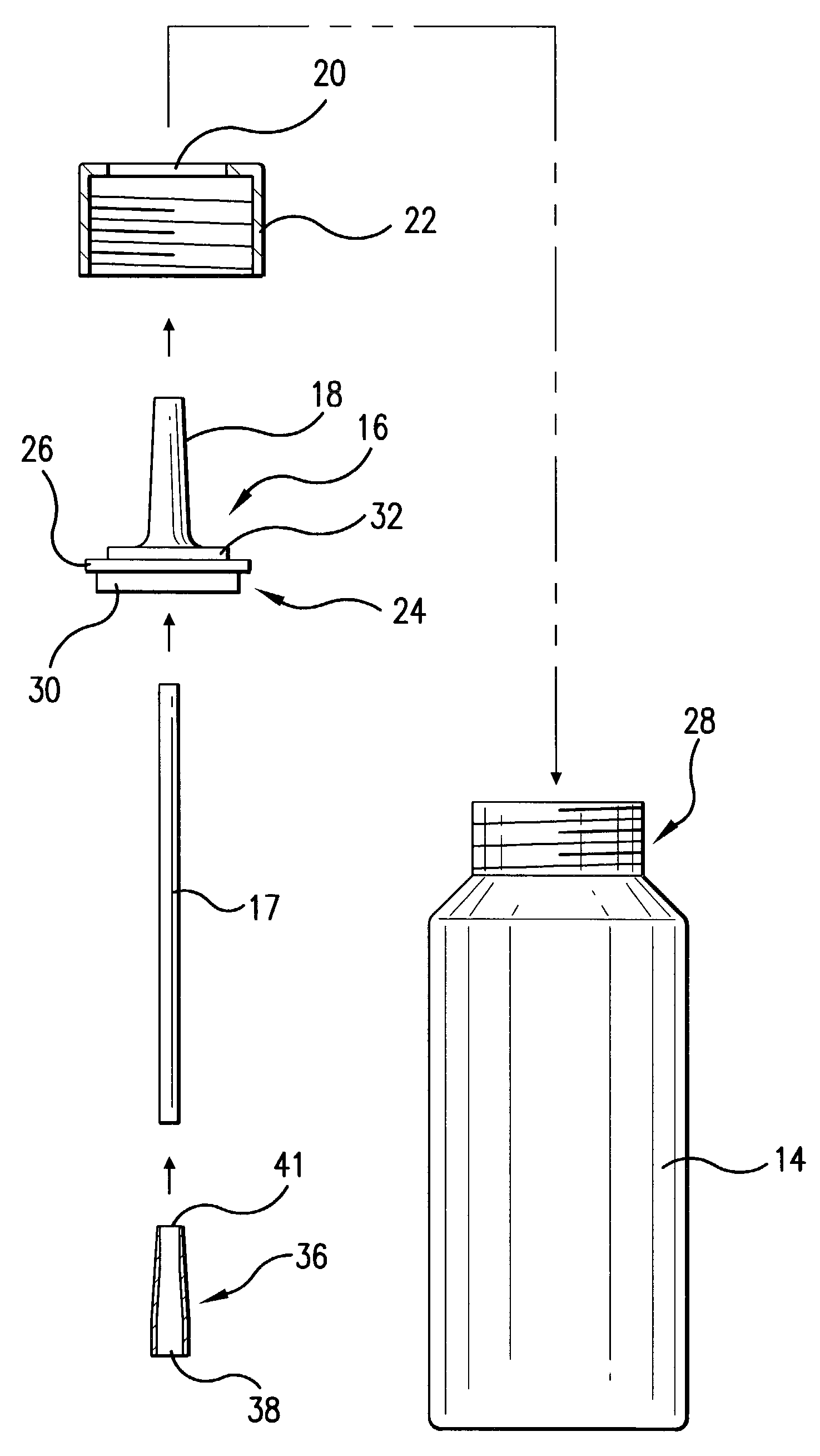
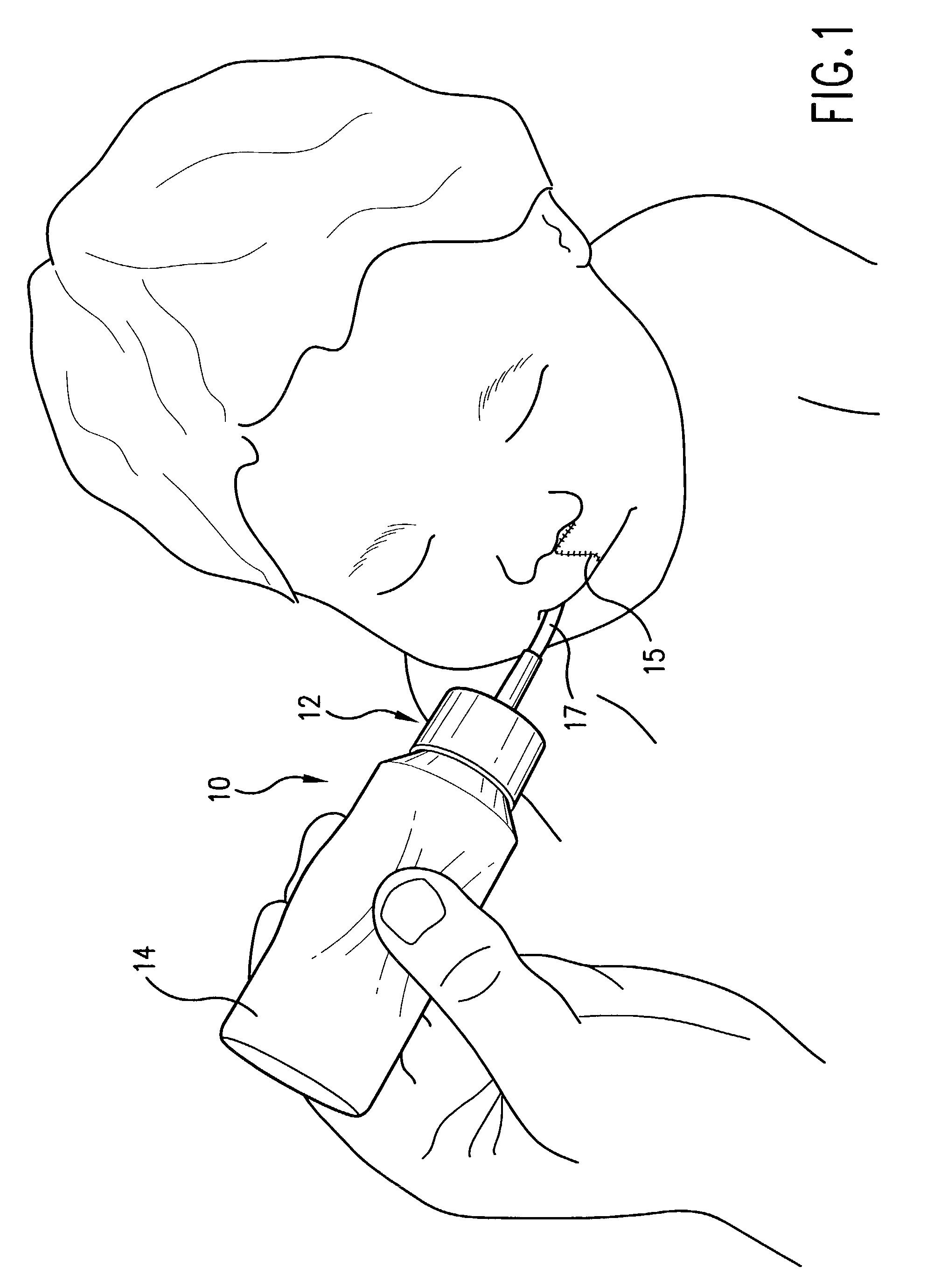
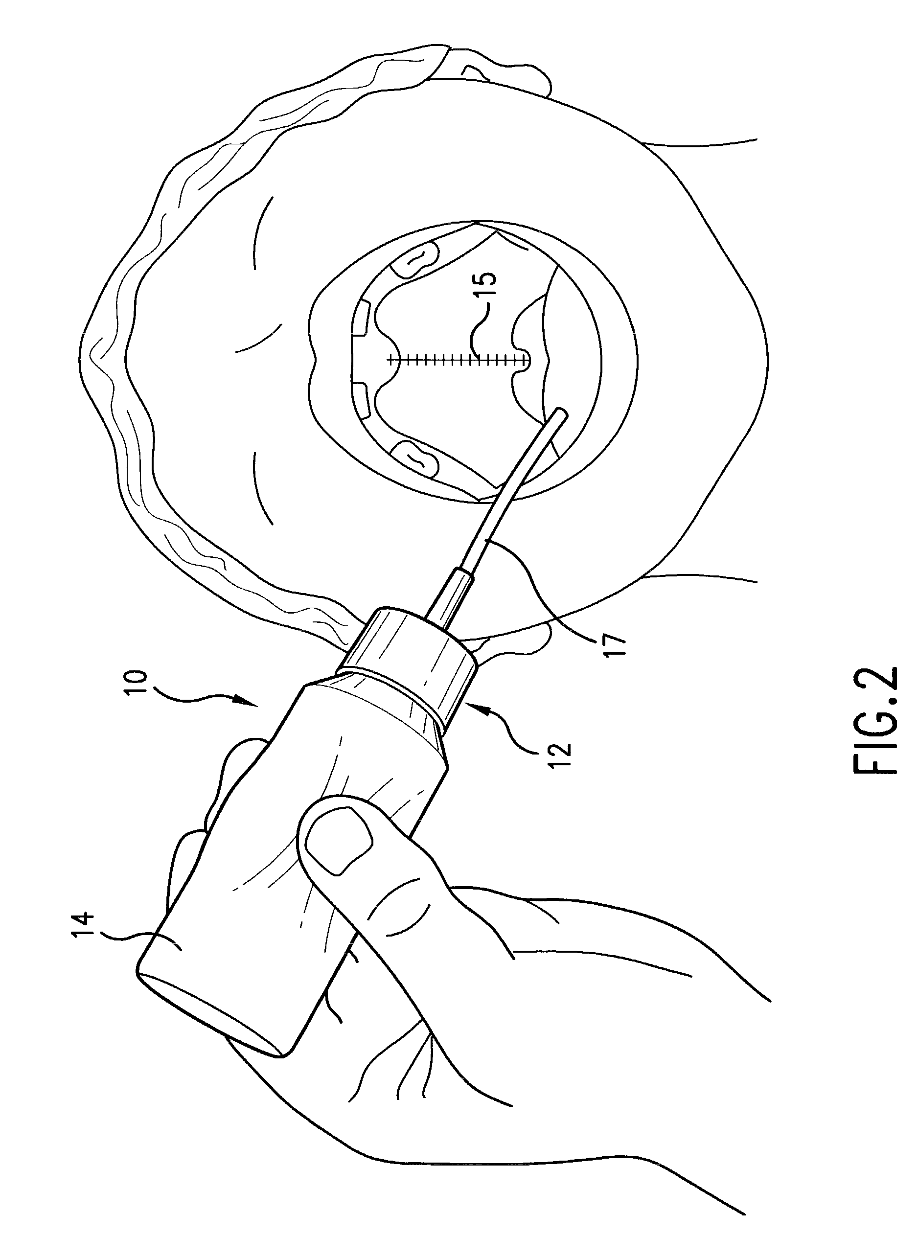
[0062]For the first embodiment, the assembled, squeezable bottle device 10 is shown in FIG. 5. To assemble the bottle device of this embodiment, the upper end 41 of the flared tubing section 36 is pushed onto the lower end of the tubing 17. As indicated by the arrows in FIG. 3, the upper end of the tubing 17 is pushed through the central aperture of the spout 16. The upper spout portion 18 is pushed through the collar aperture 20. The upper spout portion 18 extends above the collar 22, while the lower spout portion 24 remains within the collar 22. The collar 22 is then screwed onto the neck 28 of the filled bottle portion 14 and the bottle device 10 is ready for use.
second embodiment
Assembly-Second Embodiment
[0063]For the second embodiment 40 of FIG. 4, the assembled squeezable bottle device is shown in FIG. 6. To further assemble the bottle device of this second embodiment, the enlarged end 64 of the curved tubing 52 is pressed down over the straw section 54. The sharp lower end 60 of the straw section is inserted into the self-closing slit 62 in the soft end of the nipple 44. The curved tubing 52 is easier to place in the baby's mouth when the baby is held in one arm and the bottle portion is held at a 45 degree angle with the caregiver's opposite hand. The nipple assembly provides a natural appearance, which is comforting to the caregiver and visitors, and it is soft to the touch so that it can safely brush against the child's face or be grasped by the child.
[0064]For the embodiments of both FIGS. 5 and 6, when the caregiver tips the bottle device downward, fluid flows from the bottle portion 14 into the spout 16 or nipple 44. The bottle portion is made of a...
third embodiment
[0065]FIG. 7 shows an upper portion of a third alternate embodiment 66 of the present invention. This spout 68 has an extended upper spout portion 70, with three cut marks 71–73 marked on the outside of the upper spout portion 70. The cut marks indicate where the extended spout 68 can be cut, using a conventional cutting instrument, to obtain different rates of flow of the fluid in the bottle device. The upper cut mark 71 would be used to obtain a smaller diameter orifice for feeding an infant, or where the fluid is thin, for example. The lowest cut mark 73 could be used where a viscous fluid, such as a thick medication, is to be administered, or where the child is older and a liquefied blend of food is being fed to the child. Ideally, instructions would be given with the bottle device regarding the cut marks.
[0066]Continuing with FIG. 7, in this third embodiment 66, a lower portion of the extended spout 68 includes a flange 74 under a base 75. The base 75 has a greater diameter tha...
PUM
 Abstract
Description
Claims
Application Information
 - R&D
- Intellectual Property
- Life Sciences
- Materials
- Tech Scout
- Unparalleled Data Quality
- Higher Quality Content
- 60% Fewer Hallucinations
Browse by: Latest US Patents, China's latest patents, Technical Efficacy Thesaurus, Application Domain, Technology Topic, Popular Technical Reports.
© 2025 PatSnap. All rights reserved.Legal|Privacy policy|Modern Slavery Act Transparency Statement|Sitemap|About US| Contact US: help@patsnap.com


