Spillage containment system and kit for underground storage tanks

a technology for underground storage tanks and containment systems, applied in the field of underground storage tank containment systems and kits, can solve the problems of contaminated fill locations, deterioration, and aging of underground storage tanks, and achieve the effect of eliminating potential and reducing the collection point of spillag

Inactive Publication Date: 2007-02-06
OBRIEN PATRICK E
View PDF32 Cites 29 Cited by
  • Summary
  • Abstract
  • Description
  • Claims
  • Application Information

AI Technical Summary

Benefits of technology

[0019]Accordingly, it is an object of the present invention to provide a secondary spillage containment system and kit, which when outfitted upon an underground storage tank assembly functions to isolate matter commonly associated with underground storage tank systems. The present invention thus attempts to address the problems previously noted regarding state of the art overspill containment systems, including lengthy delays or oversight in being advised of a spillage problem. It is noted that the liability of a spill remains with the tank owner. With the present invention, the tank owner is made aware of a spill immediately by notification (alarm at TMS / Pod detector) and the spill will be contained in a secondary spillage containment chamber until it is removed (the spill must be removed / cleaned to reset the sensor).
[0020]Further objects of the present invention are to address the above-listed shortcomings of the prior art, as follows: 1) The access opening of the secondary spillage containment system (Spillpod) will be at least twice the size of current OS device openings, allowing a larger collection point of spillage. 2) The design features of the Spillpod kit (water elimination drain system, and debris collection trays) will eliminate the potential of water, silt, and debris from accumulating around the Spillpod, thus the interior of the Spillpod will be clean and debris free, which serves to protect or isolate the OS device inside of the Spillpod, which will also be clean, functional, and debris free. 3) The area in outside adjacency to the OS will be a secondary containment device (SP) capable of catching and containing any spillage that should occur. 4) The area intermediate the SP and an isolation wall can be closed using a wedge / ring. Optionally, the noted area may also be open to allow water to drain, yet still collect any hazardous liquids with a liquid / debris / absorbent sock tray. The tray may hold an absorbing material (sock) that will not hold water, but will hold hazardous liquids. The area between the SP and the isolation wall will allow movement of the underground storage tank, or concrete slab that may occur over time due to settling without stress being applied to the SP (the SP will be connected to the tank, but not connected to the concrete slab).
[0023]To achieve these and similar other readily ascertainable objectives, the present invention provides a secondary spillage containment kit that will secondarily contain an existing overspill containment device, and comprise certain means for receiving certain chamber-monitoring sensors. The kit also includes a new type of manhole assembly with water / silt elimination means and an add-on or secondary manhole assembly for housing / protecting certain electrical connection(s) of the chamber-monitoring system externally to the secondary spillage containment (chamber). The secondary spillage containment system of the present invention, nick-named “Spillpod,” has new design features that will address problems that exist at current underground storage tank fill locations. The Spillpod will allow the immediate notification of a problem (spillage, water entrance, via sensors located in select chambers, which sensors are in communication with a remotely-located tank monitoring system or Pod Detector (inside of the primary building TMS, or the exterior of the building with an externally mounted Spillpod detector) at the underground storage tank fill location.

Problems solved by technology

Those experienced with underground storage tanks and the maintenance thereof must often address the fact that many of the underground storage tanks suffer from aged, deteriorated, and contaminated fill locations.
Often, however, the conditions surrounding the underground storage tanks are in violation of any number of local, state, and / or federal laws.
As time has gone by many of the OS devices have started to show wear and attendant contamination.
Existing OS devices thus, do not come close to offering a complete solution to the spillage, leakage, and contamination problems that still exist at underground storage tanks.
It then follows that a great deal of petroleum product enters and contaminates groundwater supplies.
Current methods of containing spillage at the fill location of underground storage tanks by an overspill device are lacking in certain respects.
The most notable problems may be listed, as follows: 1) a relatively small 9–10 inch opening at the top of the OS device (the small opening does not allow much room for delivery error or missed spillage.
3) The water / silt build up also damages the lid assembly and components of the OS device (making the initial water tight capability obsolete, and thus allowing debris, silt, or water to infiltrate the OS device, thus damaging the drain device of the OS device, and thus the probability of the water, silt, and debris infiltrating the UG storage tank.
Spillage of even the smallest amounts will build up over the lifetime of the underground storage tank system and will create certain far-reaching environmental problems.
5) Most currently used OS devices do not have means for containing, monitoring, or receiving notification of spillage or water infiltration with the use of the OS device.
It is noted that while the prior art attempting to address secondary containment of underground fill / overfill area is somewhat well-developed, it is further noted that the most spill-prone area of the underground storage tank system (namely, the fill, overspill area) frequently does not benefit from secondary containment for various reasons.
It will be seen from a further review of the above-referenced patents and other prior art generally known to exist relating to underground storage tank spillage containment systems, that the prior art does not teach a secondary spillage containment system comprising a double-walled manhole skirt assembly in combination with a secondary spillage containment assembly as concentrically situated about primary spillage containment and tank-accessing means.
Further, the prior art does not teach a matter isolation kit installable upon an underground storage tank assembly comprising a tank access conduit (peripherally encased by primary spillage containment) for secondarily containing spillage, for sealing the secondary containment, and for isolating the various containment or isolating structures from foreign matter coming into contact with the outfitted underground storage tank assembly.

Method used


Image

  • Spillage containment system and kit for underground storage tanks
  • Spillage containment system and kit for underground storage tanks
  • Spillage containment system and kit for underground storage tanks

Examples


Embodiment Construction

)

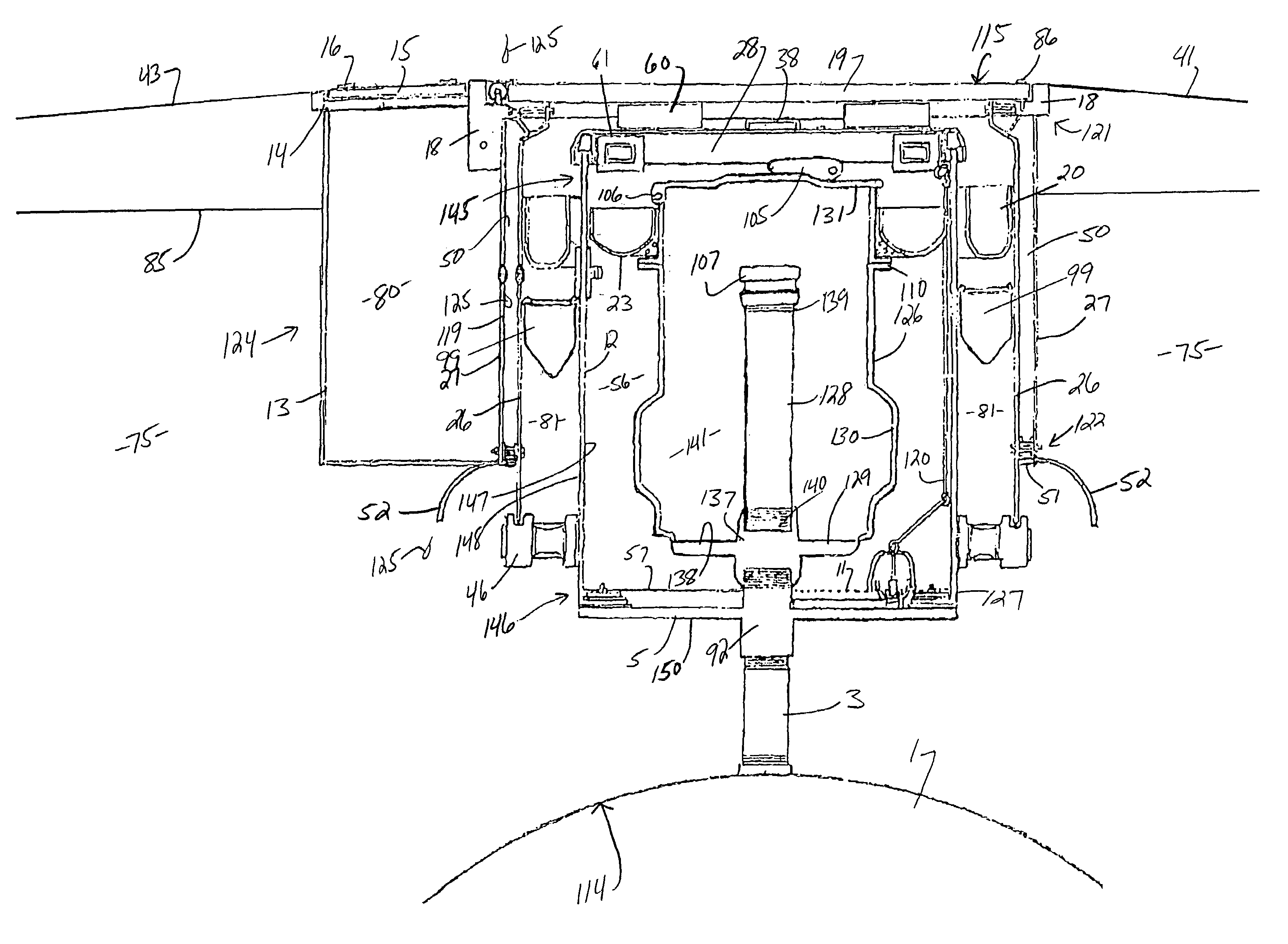
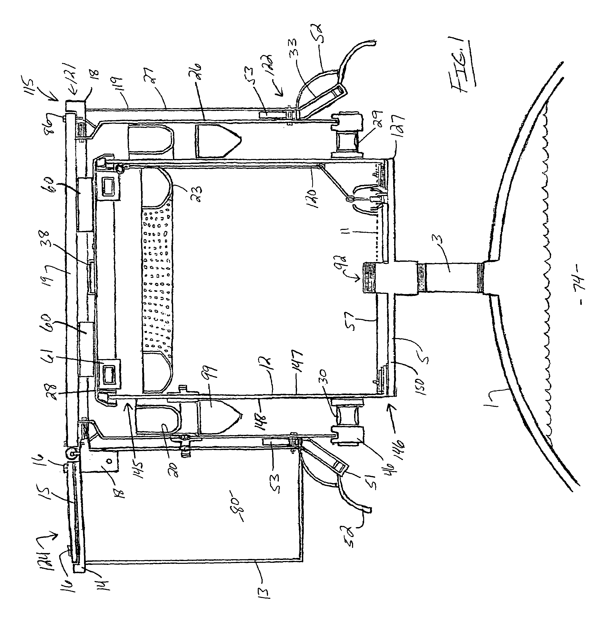
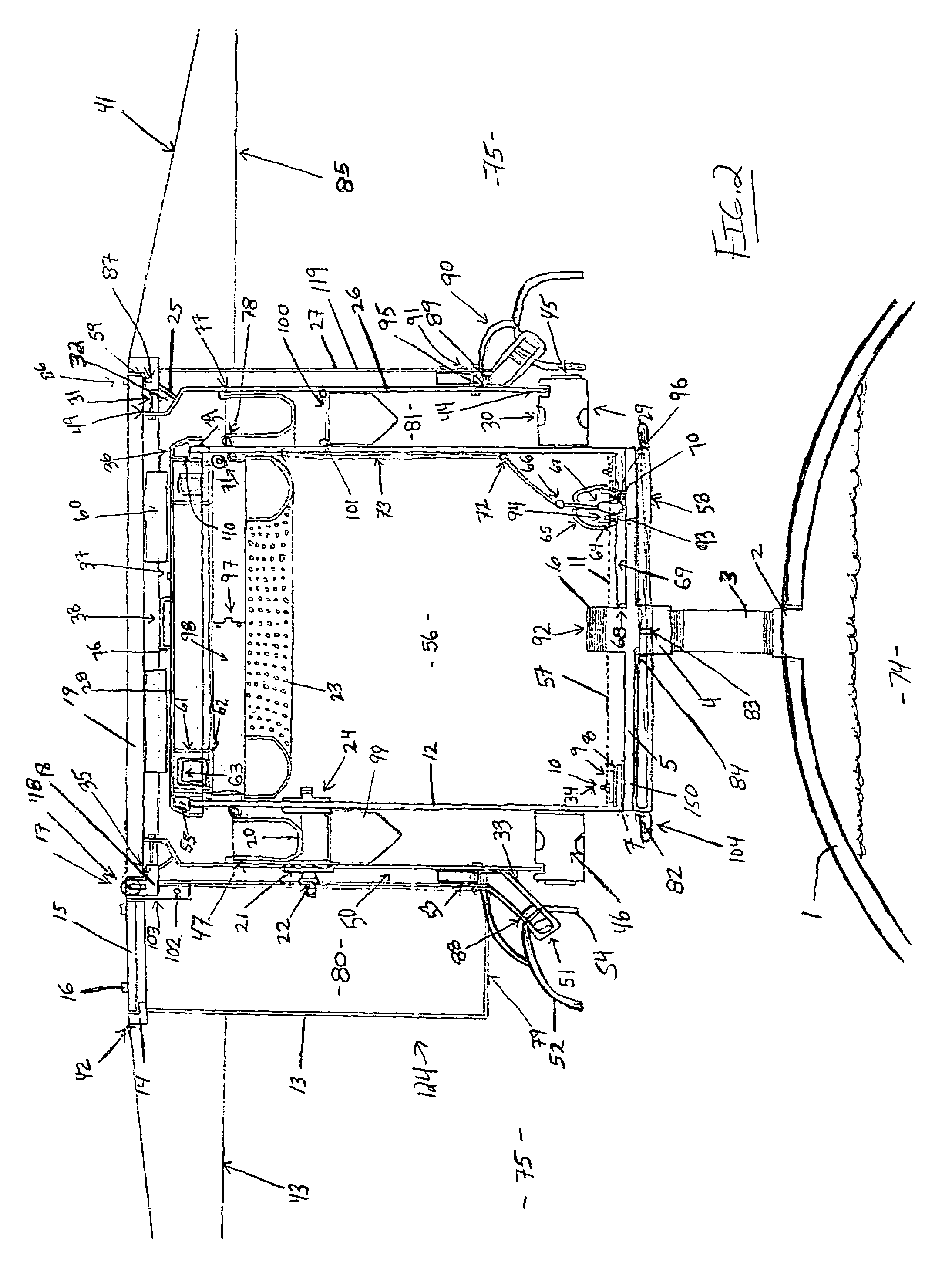
[0224]Referring now to the drawings, a preferred embodiment of the present invention concerns spillage-containing means for isolating certain matter from adjacent compartments or regions commonly associated with underground storage tanks. The spillage-containing means or matter-isolating means are defined, in part, by a spillage containment system comprising certain spillage containment assemblies and a unique manhole assembly. The present invention thus discloses a spillage containment system for use in combination with an underground storage tank assembly comprising a storage tank 1 as illustrated and referenced in FIG. Nos. 1, 2, 5, 6, 8–10, and 17; a tank access conduit 3 (preferably a 4-inch pipe nipple (cut to length per application)) as illustrated and referenced in FIG. Nos. 1, 2, 5, 6, 8–10, and 17. From a general consideration of the noted figures and from a particular inspection of FIG. No. 2, it will be seen that tank access conduit 3 preferably comprises male threads a...


PUM

PropertyMeasurementUnit
Flexibilityaaaaaaaaaa

Abstract

A matter-isolating system for use in combination with an underground storage tank assembly comprises primary and secondary spillage containment assemblies and a double-walled manhole assembly. The manhole assembly comprises a manhole lid, an outer skirt wall, and an inner skirt wall. The inner skirt wall defines an inner manhole cavity and an outer manhole channel. The outer manhole channel directs moisture from the lid to certain backfill material thus isolating the inner manhole cavity from channel-directed moisture. The spillage containment assemblies form concentric primary and secondary spillage-containing chambers in radial adjacency to a tank access conduit of the underground tank assembly. The inner manhole cavity functions to isolate the secondary spillage containment chamber from the outer manhole channel and the primary spillage containment chamber isolates the secondary spillage containment chamber from the tank access conduit. A chamber-monitoring system may be incorporated into the system for monitoring the isolated chambers.

Description

BACKGROUND OF THE INVENTION[0001]1. Field of the Invention[0002]The present invention generally relates to a matter containment system for use in combination with an underground storage tank. More particularly, the present invention relates to a secondary spillage containment system or kit for outfitting an underground storage tank assembly having primary spillage containment.[0003]2. Description of the Prior Art[0004]Those experienced with underground storage tanks and the maintenance thereof must often address the fact that many of the underground storage tanks suffer from aged, deteriorated, and contaminated fill locations. The effects of petroleum products entering, and contaminating ground water from spills, and leaks is well documented and there is a great deal of documentation detailing the negative effects of contaminated ground water. Obviously, if a leak or spill can be prevented the environment will benefit. In an effort to protect the environment from leaks and spills of...

Claims


Application Information

Patent Timeline
IPC IPC(8): B65B1/04
CPCB65D90/24B65D90/10
Inventor O'BRIEN, PATRICK E.
Owner OBRIEN PATRICK E
Why Eureka
Try Eureka