
Drive system for a railway hopper car discharge gate

a technology for hopper cars and discharge gates, which is applied in the direction of railway components, tipping wagons, wagons/vans, etc., can solve the problems of affecting the operation of the discharge gate. achieve the effect of preventing shaft deflection

Active Publication Date: 2007-02-06
AERO TRANSPORTATION PRODS
View PDF50 Cites 16 Cited by
  • Summary
  • Abstract
  • Description
  • Claims
  • Application Information

AI Technical Summary

Benefits of technology

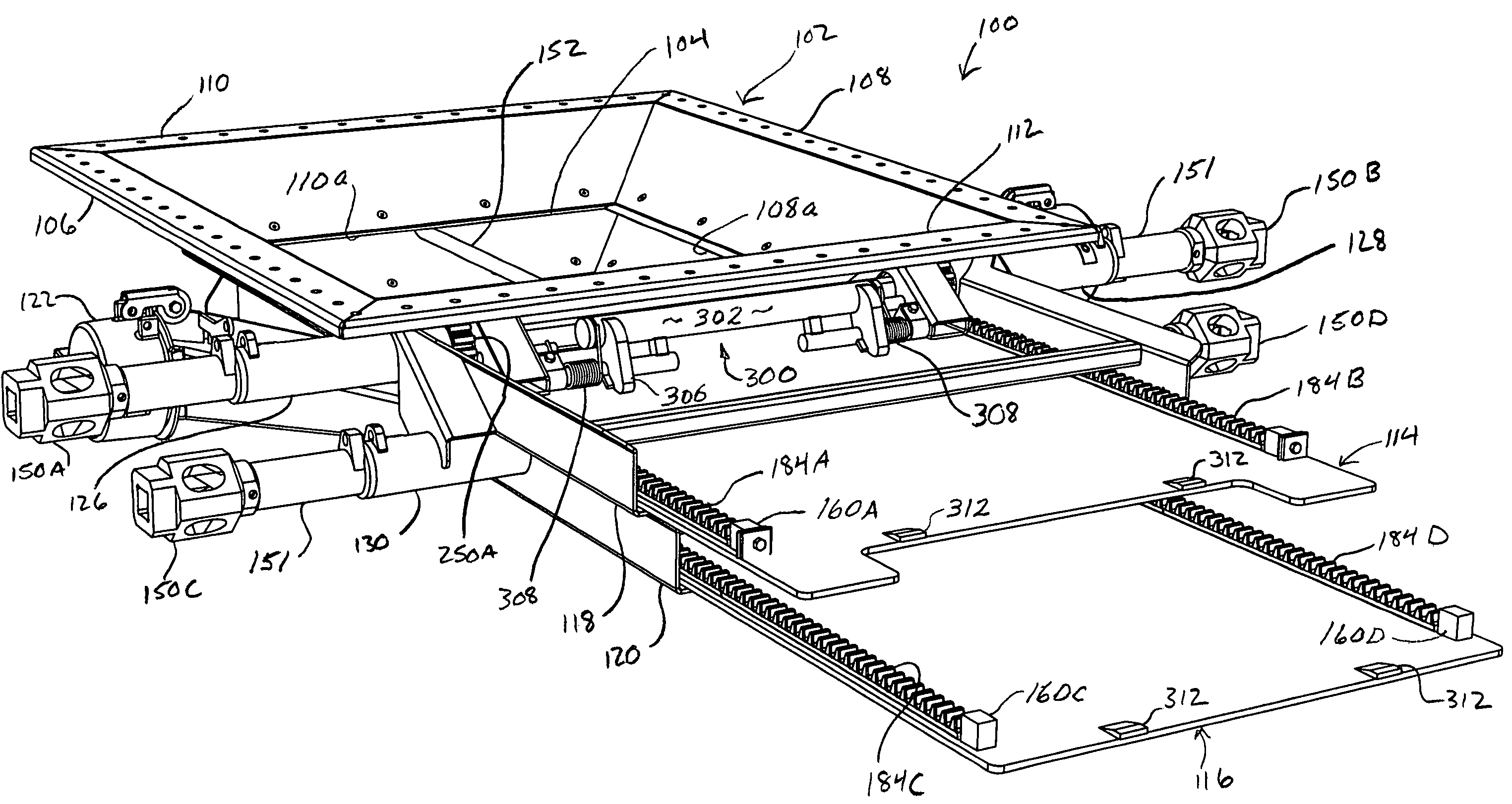
[0007]In one aspect of the invention, a drive system for a railway hopper car discharge gate provides a controlled, rack and pinion driven sliding motion for a discharge gate door panel. The discharge gate includes a hopper frame surrounding a central opening. The door panel is movable between frontward and rearward positions to open or close the gate, respectively. A drive shaft passes through the hopper frame transverse to the direction of travel of the door panel, and has a pinion thereon in engagement with an associated rack. The working surfaces of the pinion teeth present a generally cylindrical profile in a plane orthogonal to of the axis of rotation of the pinion, whereby conjugacy may be maintained between the pinion teeth and the rack teeth even as the distance between rack and pinion varies during operation of the drive system. Stop blocks at the respective ends of each rack are sized and positioned to convert pinion torque to a vertical force applied to and opposed by the panel to thereby prevent further travel without damaging drive system components.
[0008]In another aspect of the invention, a socket or other means for inducing drive shaft rotation is mounted on an outer end of the drive shaft. A bearing spacer is slidably mounted on the drive shaft between the socket and the pinion. The bearing spacer is a hollow sleeve that supports the drive shaft and substantially prevents shaft deflection under rotational load.
[0009]In a further aspect of the invention, an inertia brake is provided and includes a counterweight mounted on a pivotal arm that has a normal position in which a portion of the arm extends downwardly in front of the leading edge of the door panel of a discharge gate to block forward movement of the panel to an open position in response to a forward force caused by a rapid cessation of movement of the hopper car. Normal opening of the door panel to discharge transported material is not prevented by the brake as the absence of an abnormal force permits the arm to swing to a fully released position as the panel shifts to its open position, and then return to the normal, braking position as the panel is closed.

Problems solved by technology

Because of its length, as the shaft turns it is subject to undesirable transverse deflection.
Additionally, a stop at each end of the rack is engaged by the pinion to limit the travel of the panel, which may cause an impact that can damage the drive components or produce excessive wear over time.
The weight of the lading in a full hopper car can exert considerable downward force against the door panels causing them to deflect as well as resist movement under load.
As the pinion moves towards or away from the rack the effective pitch of the pinion teeth is changed and thus the rack teeth and pinion teeth may no longer align properly.
In particular, the door is subject to inertial forces that would tend to cause it to open when the hopper car is stopped suddenly.

Method used


Image

  • Drive system for a railway hopper car discharge gate
  • Drive system for a railway hopper car discharge gate
  • Drive system for a railway hopper car discharge gate

Examples


Embodiment Construction

Double-Door Discharge Gate

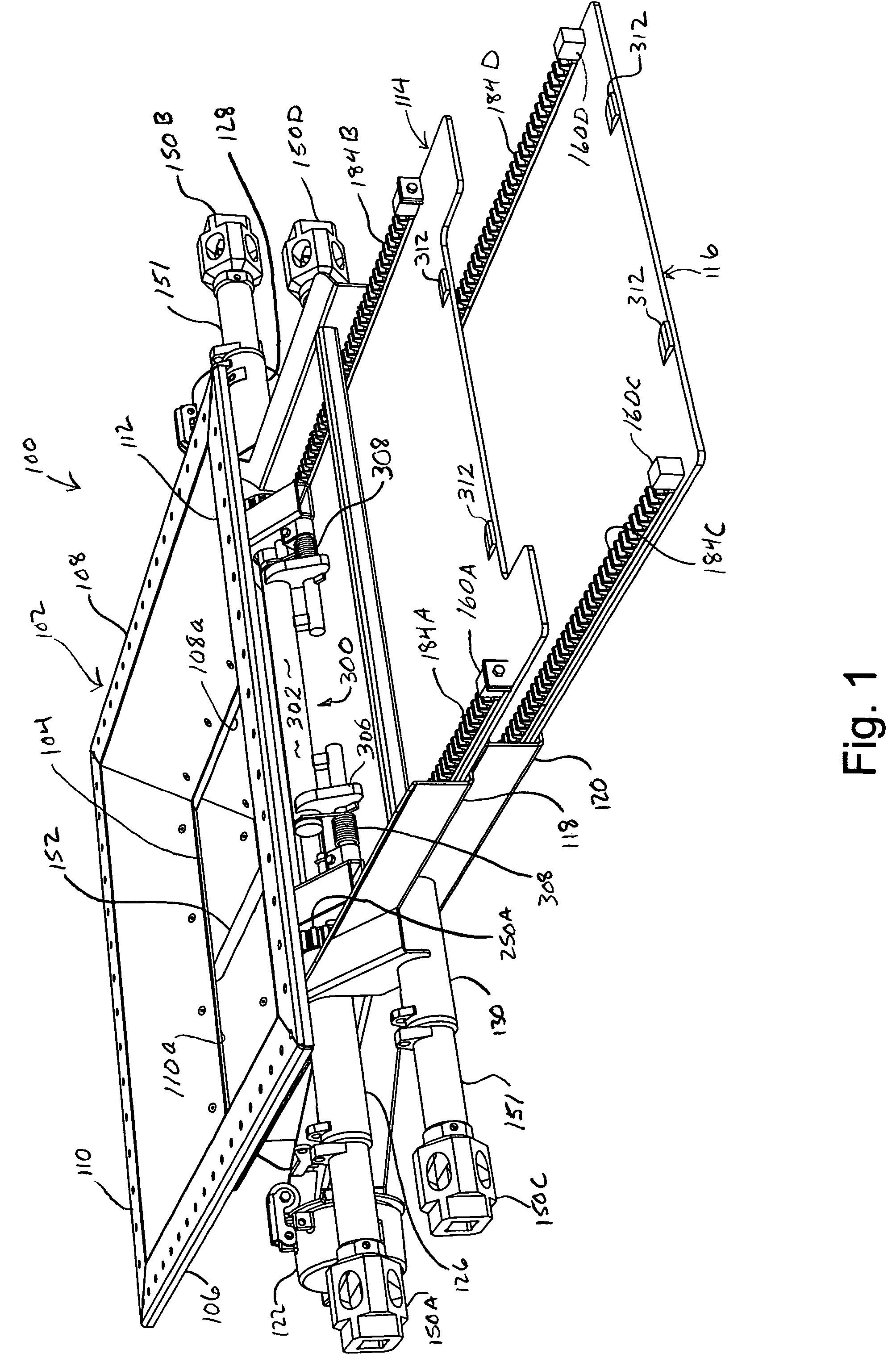
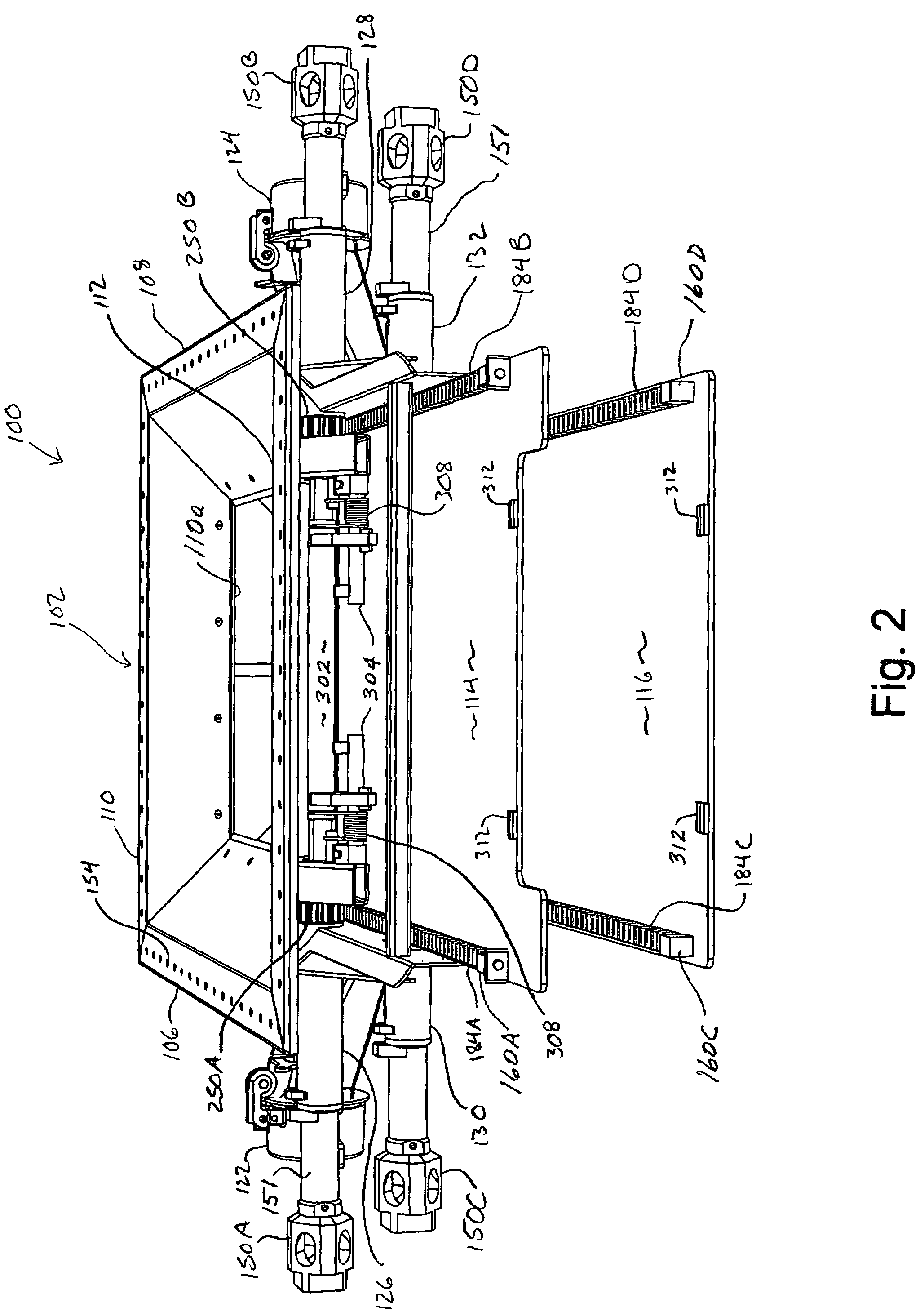
[0034]Referring now to the drawings, and initially in particular to FIGS. 1–3, wherein like reference numerals indicate like parts throughout the several views, a railroad hopper car discharge gate 100 is illustrated for the purpose of describing an embodiment of the drive system of the present invention. The discharge gate 100 includes a generally rectangular upper frame or hopper 102 surrounding a generally rectangular, central discharge opening 104 (see FIG. 3). The upper frame 102 includes four upper sidewalls 106, 108, 110 and 112. Each of the sidewalls 106, 108, 110, and 112 has a lower, inner edge that, in combination, define the discharge opening 104 (lower edges 106a, 108a and 110a are visible in FIGS. 1–3). The discharge gate 100 is provided with an upper door panel 114 and a lower door panel 116 that slide fore and aft between open and closed positions within respective middle 118 and lower 120 frames. Upper panel 114 is shown partially open; low...


PUM


Abstract

A drive system for a railway hopper car discharge gate includes a door panel operated by a rack and pinion drive. The pinion teeth present a substantially cylindrical profile in a plane orthogonal to the axis of pinion rotation. The cylindrical tooth profile substantially prevents the pinion teeth from skipping or walking against the rack teeth when the spacing between the pinion and the door panel and associated rack fluctuates during operation of the discharge gate. Pinion torque is converted into a vertical force at the ends of travel of the door panel to prevent damage to the drive components. A bearing arrangement supports a drive shaft that is operated to rotate the pinions, and minimizes deflection of the shaft when under rotational load. An inertia brake is provided to engage the door panel and prevent it from opening upon a rapid stop of the hopper car as may occur upon impact with an adjacent railway car.

Description

FIELD OF THE INVENTION[0001]This invention relates to the field of discharge gates for railway hopper cars and, more particularly, to a drive system for moving discharge gate door panels between open and shut positions.BACKGROUND OF THE INVENTION[0002]Railroad hopper cars are used to transport bulk lading through railway systems. A railroad hopper car typically includes discharge gates located on the underside of the car for unloading the transported materials. Discharge gates typically include one or more sliding door panels that may be selectively moved between open and closed positions to expose or cover an opening in the undercarriage of the car. Typically, an opening and closing drive mechanism shifts a door panel between open and closed positions via a rack or racks fixed to the panel and an operating shaft. The operating shaft carries pinions which engage the racks. The operating shaft is rotated to move the panel in the desired direction. The car may be unloaded by sliding t...

Claims


Application Information

Patent Timeline
Patent Type & Authority Patents(United States)
IPC IPC(8): B61D3/00B61D7/20B61D7/30
CPCB61D7/30B61D7/20
Inventor EARLY, STEPHEN R.
Owner AERO TRANSPORTATION PRODS
Learn More