Eureka AIR delivers breakthrough ideas for toughest innovation challenges, trusted by R&D personnel around the world.

Exhaust system for multi-cylinder engine, and straddle-type vehicle provided with same

a multi-cylinder engine and exhaust system technology, which is applied in the direction of air intakes for fuel, machines/engines, combustion air/fuel air treatment, etc., can solve the problems of increasing the number of parts and gas pressure not being sufficient to achieve the desired dynamic effect, etc., to achieve enhanced output characteristics, simple construction, and reduced space in the vehicle

Inactive Publication Date: 2007-02-06
YAMAHA MOTOR CO LTD
View PDF9 Cites 19 Cited by
  • Summary
  • Abstract
  • Description
  • Claims
  • Application Information

AI Technical Summary

Benefits of technology

The present invention provides an exhaust system for a multi-cylinder engine that reduces the number of parts, improves layout flexibility, and increases engine performance in low- and middle-speed ranges. The exhaust system includes a collecting pipe with a front-end portion, middle portion, and rear-end portion, where the middle portion has an exhaust control module for controlling the area of the exhaust passages in accordance with engine conditions. The exhaust control valve can be controlled based on engine conditions, detected by a detection device, and a target value computing device can be used to compute the target value of the exhaust control valve opening. The exhaust system allows for a reduction in the number of parts, arrangement in reduced space, and improvement in engine performance.

Problems solved by technology

Therefore, the housing for containing the exhaust control valves is increased in size, resulting in the increased number of parts.
In the prior art exhaust system having the valve mechanism (exhaust control valve) provided forwardly of the silencer, layout flexibility is improved; however, since the valve mechanism (exhaust control valve) is positioned away from the engine, the exhaust gas pressure is not sufficient to obtain the desired dynamic effect, thereby leaving opportunity for further improvement in performance.

Method used


Image

  • Exhaust system for multi-cylinder engine, and straddle-type vehicle provided with same
  • Exhaust system for multi-cylinder engine, and straddle-type vehicle provided with same
  • Exhaust system for multi-cylinder engine, and straddle-type vehicle provided with same

Examples


Embodiment Construction

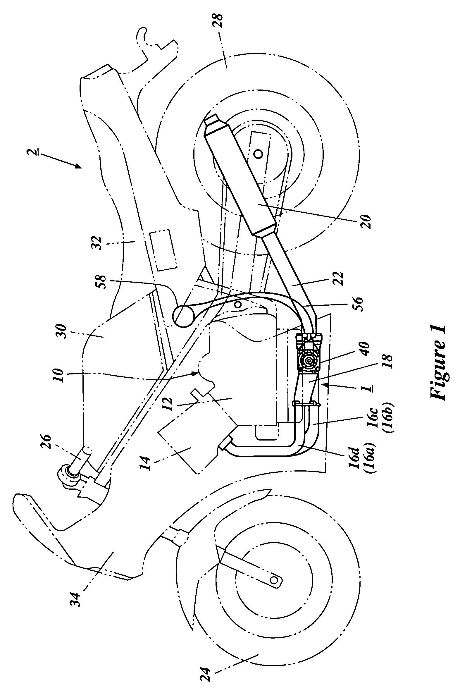
[0038]With reference to the figures, preferred embodiments are described below in detail. FIG. 1 shows an example of one of straddle-type vehicle with which embodiments of the present inventions can be used, and in particular, a motorcycle 2, with an exhaust system 1 for a multi-cylinder engine.

[0039]As shown in FIG. 1, the motorcycle 2 has a front wheel 24, a steering handlebar 26, a rear wheel 28, a cover 30 for covering an intake cleaner and a fuel tank, a driver's seat 32 and a cowling 34. A four-stroke, four-cylinder engine 10 is located in the central portion of the body, however, other types of multi-cylinder engines can also be used. The engine 10 has a cylinder bank 14 extending obliquely upward toward the front from a crankcase 12, although other cylinder orientations can also be used. The exhaust system 1 extends from the cylinder bank 14 at the front side of the vehicle and is routed along under the engine 10.

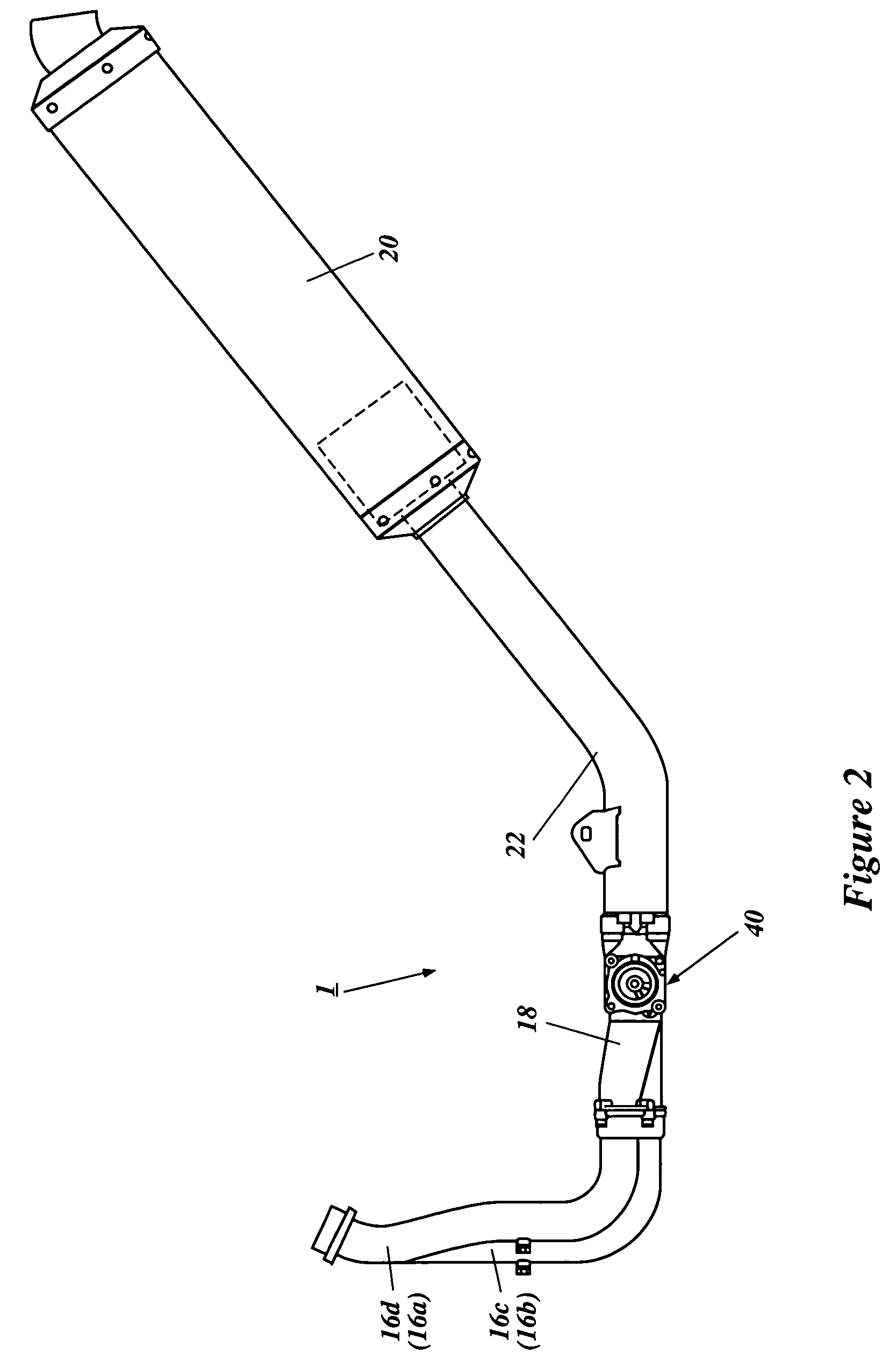
[0040]An overall view of the exhaust system 1 is shown in FIG....


PUM


Abstract

An exhaust system for a multi-cylinder engine can include a plurality of exhaust pipes with first upstream ends connected to exhaust openings of a multi-cylinder engine, and a collecting pipe connected to the second downstream ends of the exhaust pipes for collecting exhaust introduced from the exhaust pipes and directing it to a silencer. The collecting pipe has a front-end portion communicated to exhaust passages of the exhaust pipes, a middle portion for collecting the exhaust introduced from the front-end portion, and a rear-end portion for further collecting the exhaust introduced from the middle portion. The middle portion is provided with exhaust control means for controlling the area of the exhaust passages in accordance with engine speed.

Description

PRIORITY INFORMATION[0001]This application is based on, and claims priority to, Japanese Patent Application No. 2003-295804, filed Aug. 20, 2003, the entirety of which is expressly incorporated by reference herein.BACKGROUND OF THE INVENTIONS[0002]1. Field of the Inventions[0003]The present inventions relate to an exhaust system for a multi-cylinder engine powering a straddle-type vehicle, and in particular, exhaust systems that are adapted to control the area of exhaust passages in accordance with engine conditions.[0004]2. Description of the Related Art[0005]In four-stroke engines, two-stroke engines and the like, it is known that opening and closing of an exhaust valve introduces exhaust into an exhaust pipe intermittently, where an inertia effect and a pulsation effect of the exhaust are produced. These effects (hereinafter called a “dynamic effect”) change in accordance with engine conditions (mainly engine speed).[0006]Therefore, maximizing the dynamic effect to increase volum...

Claims


Application Information

Patent Timeline
Patent Type & Authority Patents(United States)
IPC IPC(8): F01N7/10F01N13/08F01N13/10F02B27/06F02B29/06F02D9/04F02D9/06F02D9/10F02M35/10
CPCF01N13/08F02B27/06F02D9/04F02D9/06F02D9/103F02B29/06F01N2240/36F01N2340/04F01N2590/04Y02T10/146F02M35/162Y02T10/12
Inventor TERASHIMA, YASUTO
Owner YAMAHA MOTOR CO LTD
Why Eureka
Eureka Blog
Learn More