Laser device

a laser device and laser technology, applied in the direction of laser details, optical resonator shape and construction, electrical apparatus, etc., can solve the problems of reducing the efficiency of the excimer laser device b>1, impurities occurring there staining and damage the other optical components, and achieve the effect of stable beam form and efficient oscillation of laser ligh

Inactive Publication Date: 2007-01-30
GIGAPHOTON
View PDF8 Cites 0 Cited by
  • Summary
  • Abstract
  • Description
  • Claims
  • Application Information

AI Technical Summary

Benefits of technology

[0016]The present invention is made to eliminate the disadvantages of the above art, and its object is to provide a laser device capable of efficiently oscillating laser light and always obtaining a stable beam form.
[0019]According to the above configuration, by allowing the laser light to pass through the partial reflecting portion or the non-reflective portion of the optical element, the beam form of the laser light to be outputted is shaped into the shape of the partial reflecting portion or the non-reflective portion. Recycle laser light separated by the optical element is reflected at the total reflecting portion with high reflectivity and returns to the amplifying section, where it contributes to laser oscillation. Accordingly, energy of the separated laser light is not lost, thus improving the energy efficiency of the laser device relative to the energy inputted for excitation.
[0023]According to the above configuration, by outputting the laser beam from the partial reflecting portion provided on approximately the center of the front mirror, the beam form of the laser beam is shaped. Since the total reflecting portion is provided outside the perimeter of the partial reflecting portion, the laser light passing the portion outside the partial reflecting portion is reflected at the total reflecting portion with high reflectivity and returns to the amplifying section, where it contributes to the laser oscillation again. Accordingly, the energy loss of the laser light decreases, thus improving the energy efficiency of the laser device.
[0024]Further, in the present invention, since the front mirror also plays the role of the front slit placed between the front mirror and the laser chamber in the prior art, the front slit becomes unnecessary, thus reducing the number of components. In addition, since it is not necessary to place the front slit, the distance between the front mirror and the laser chamber is reduced, thus making the resonator length of the laser device shorter. Thereby, the laser device is reduced in size, and the loss in the resonator is reduced, thus increasing the power of the laser light.
[0028]According to the above configuration, by allowing the laser light to transmit the non-reflective portion of the prism, the beam form is shaped, and the laser light entering the total reflecting portion is separated and removed. Accordingly, in the present invention, the prism plays the role of “the rear slit placed between the laser chamber and the prism” which is the conventionally ordinary configuration, thus making the rear slit unnecessary and reducing the number of components. As a result, the resonator length becomes smaller, the laser device is reduced in size and the loss in the resonator is reduced, thus increasing the power of the laser light. It should be noted that the configuration further including the front mirror in the aforementioned second configuration may be suitable. According to this configuration, the same operational effects as in the aforementioned second configuration is added.
[0036]According to the above configuration, of the laser light passing through an opening of the front slit, components which are conventionally partially reflected at the front mirror and cut by the rear slit pass through the portion with high transmissivity in the outer peripheral portion of the front mirror to be outputted outside. Accordingly, the components cut by the rear slit decrease, thus reducing the energy loss of the laser light, and improving the energy efficiency of the laser device.

Problems solved by technology

However the aforementioned prior art has the disadvantage described below.
Thus, out of the discharge energy inputted into the discharge area 18, a part of it becomes a loss such as heat or the like and is not taken out as the laser light 1, which causes the disadvantage of reducing the efficiency of the excimer laser device 1.
Furthermore, heat occurs in the areas close to the openings 16A and 17A of the slits 16 and 17 causes the slits 16 and 17 to have heat, which causes the disadvantage that impurities occurring there stain and damage the other optical components.

Method used


Image

  • Laser device
  • Laser device
  • Laser device

Examples


first embodiment

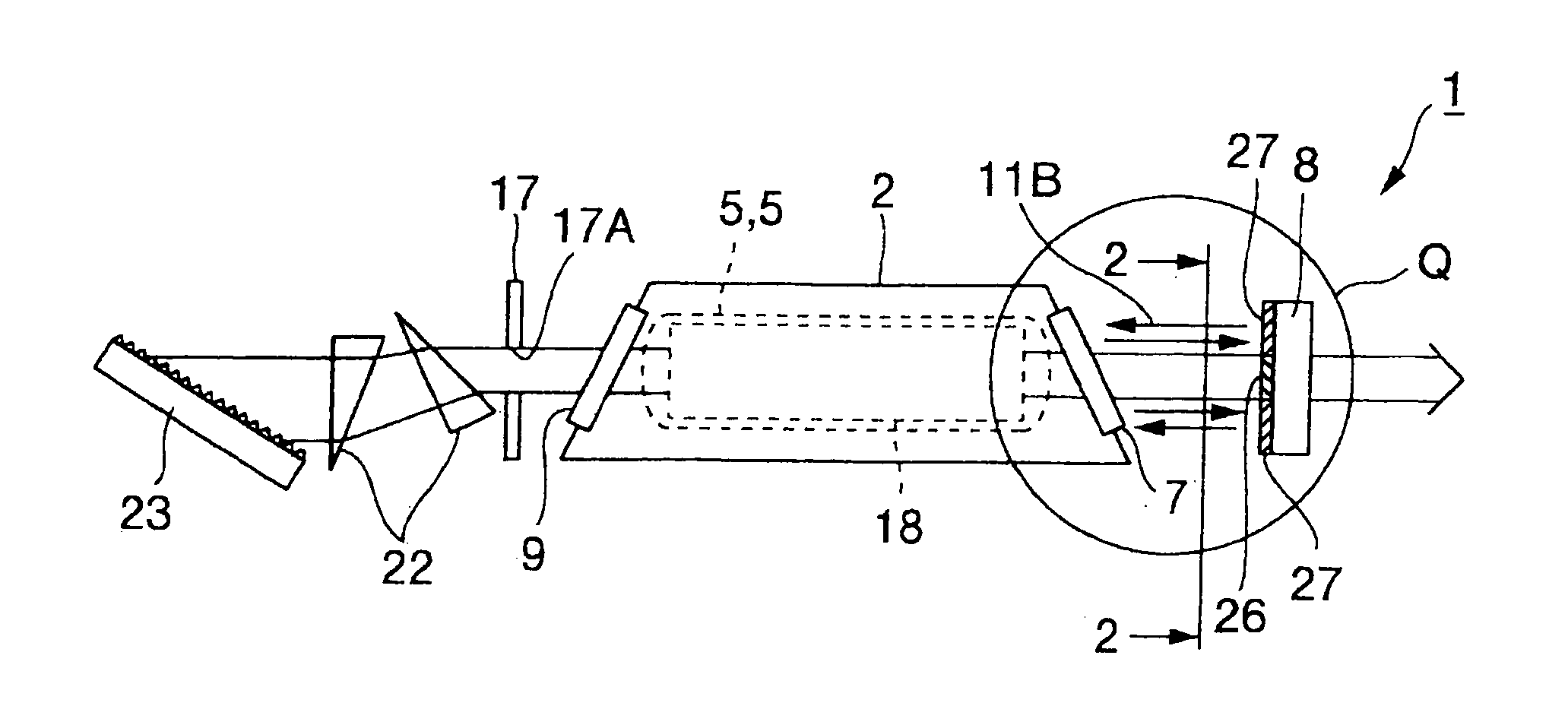
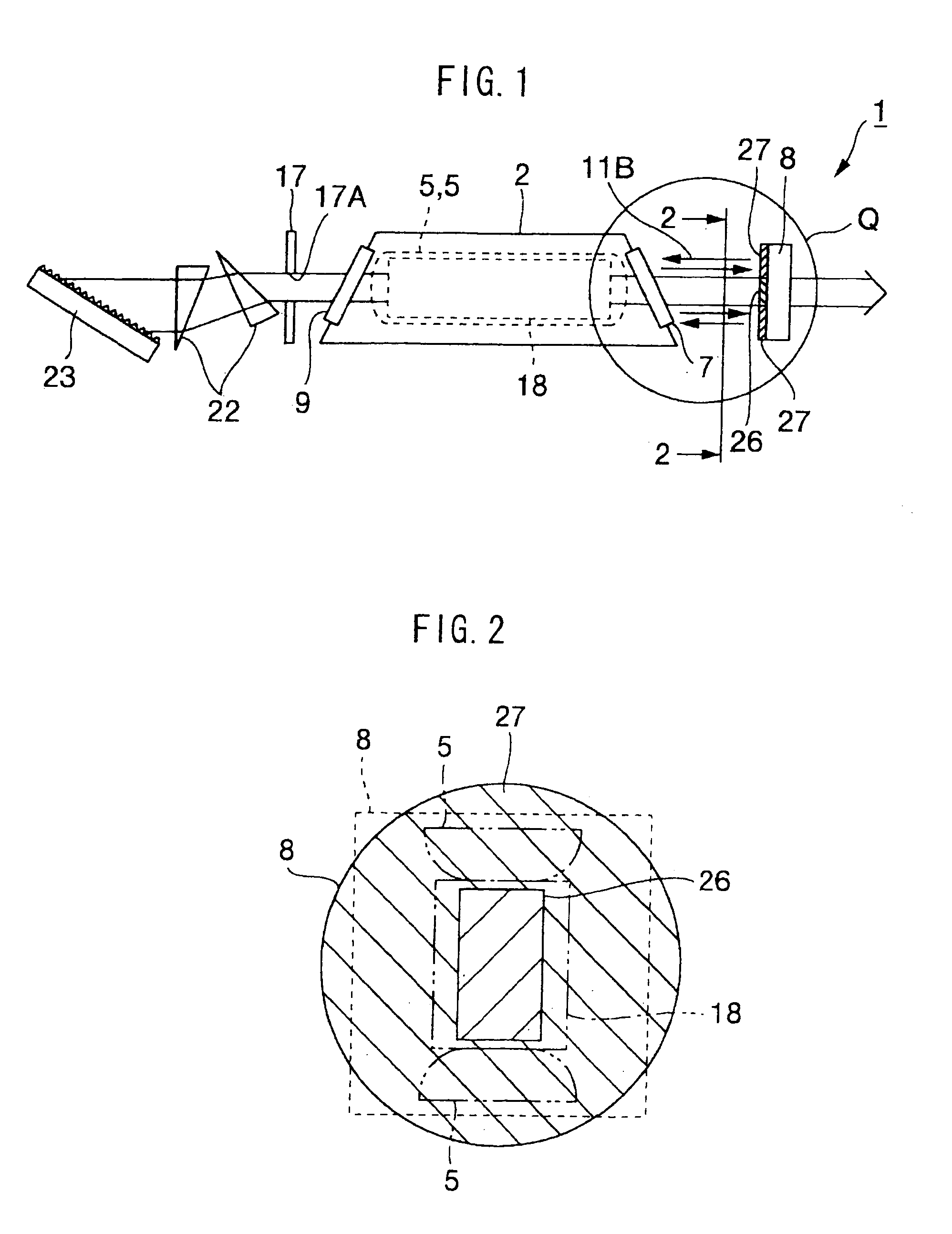
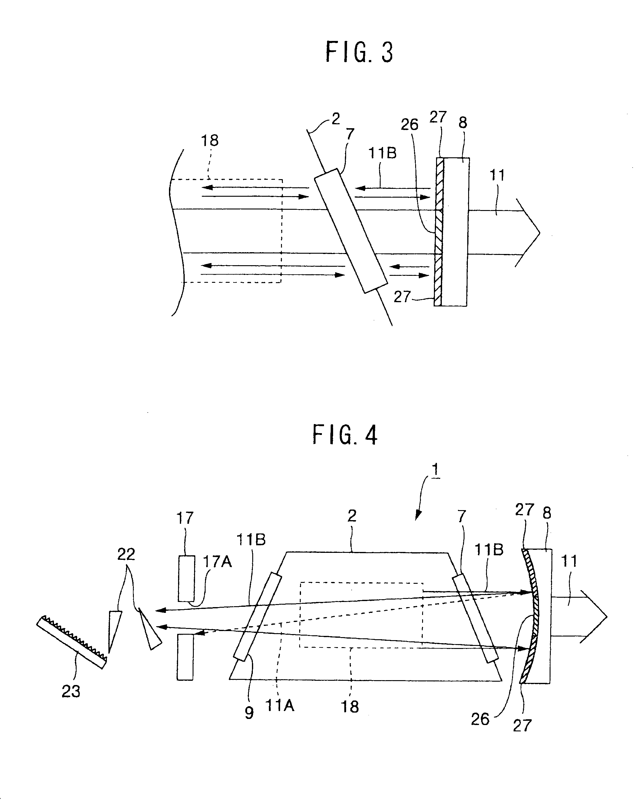
[0058]As explained above, the partial reflecting portion 26 for reflecting part of the laser light 11 is provided on approximately the center portion of the front mirror 8, and the total reflecting portion 27 for reflecting the laser light 11 with high reflectivity is provided outside the perimeter of the partial reflecting portion 26. Thus, the laser light 11 passes through the partial reflecting portion 26 to be shaped into the shape of the partial reflecting portion 26.

[0059]Of the laser light 11 oscillated by discharge, the recycle laser light 11B not outputted is reflected by the total reflecting. portion 27 to return to the inside of the laser chamber 2, where it is amplified again in the discharge area 18. Accordingly, part of the laser light 11 is not thrown away as surplus laser light 11A (See FIG. 14), and of the energy inputted to discharge, the ratio of the energy which can be taken out as the laser light is increased. As a result, energy efficiency of the excimer laser...

second embodiment

[0070]On the other hand, in the second embodiment, the front mirror 8 and the discharge area 18 are initially aligned in the lateral direction, and independently of this, the front slit 16 and the discharge area 18 are aligned in the vertical direction, thus providing the characteristic in which the alignment is easy. In the above alignment, in order to align the optical axis of the laser, the positioning of the front mirror 8 is performed at first. Subsequently, the placement position of the laser chamber 2 is adjusted to correspond to the position of the front mirror 8, thereby aligning the front mirror 8 and the discharge area 18 in the lateral direction. Then the front slit 16 and the discharge area 18 are aligned in the vertical direction. Further, the partial reflecting portion 26 of the front mirror 8 is formed into a bar shape, thus reducing time and effort taken, for example, for masking during coating compared to the partial reflecting portion 26 formed into a rectangular ...

fourth embodiment

[0079]As explained above, the components 11E of the laser light 11 passing through the peripheral portion of the front opening portion 16A are not reflected by the front mirror 8, but are taken outside the excimer laser device 1. As a result, the disadvantage that the components 11C (See FIG. 14) of the laser-light 11 passing through the peripheral portion of the front opening 16A are reflected by the front mirror 8 and cut by the rear slit 17 does not occur. Accordingly, the loss of the laser light 11 decreases and the energy efficiency of the excimer laser device 1 is improved.

[0080]It is preferable to make the shape and size of the low transmission portion 29 smaller than the front opening portion 16A so that all the laser light 11D reflected at the low transmission portion 29 passes through the rear opening portion 17A. Thereby, the loss of the laser light 11 is minimized, and the energy efficiency is optimized. The size of the low transmission portion 29 may be approximately e...


PUM


Abstract

A laser device capable of efficiently oscillating laser light and always obtaining a stable beam form is provided. For this purpose, in the laser device including an amplifying section (18) in which a laser medium is amplified to oscillate laser light (11), and an optical element for separating part of the laser light (11) oscillated, and shaping a beam form of the laser light (11) into a desired form to output the same, wherein the optical element has at least either one of a partial reflecting portion (26) for partially reflecting the laser light (11) or a non-reflective portion (28) for transmitting the laser light (11) at high transmissivity, each of which is provided on approximately a center portion, and a total reflecting portion (27) which is provided outside a perimeter of the partial reflecting portion (26) or the non-reflective portion (28), and which reflects the laser light (11) at high reflectivity.

Description

[0001]This application is a Divisional of prior application Ser. No. 09 / 621,140 filed on Jul. 20, 2000 now U.S. Pat. No. 6,731,666.TECHNICAL FIELD[0002]The present invention relates to a laser device, and particularly relates to a laser device having an optical element for shaping a beam form of laser light into a desired form.BACKGROUND ART[0003]Conventionally, in a narrow band excimer laser device and fluorine laser device, a slit for shaping a sectional form of laser light into a predetermined form is known, and it is disclosed, for example, in Japanese Patent No. 2531788. FIG. 12 shows a configuration of an excimer laser device according to the prior art. It should be noted that FIG. 12 is made by being reversed horizontally relative to the drawing made in the aforementioned Patent. In FIG. 12, the excimer laser device 1 is seen from above, and in the explanation hereinafter, an up and down direction of the paper surface of FIG. 12 is called a lateral direction, and a direction ...

Claims


Application Information

Patent Timeline
Patent Type & Authority Patents(United States)
IPC IPC(8): H01S3/08H01S3/225
CPCH01S3/08009H01S3/225
Inventor KUMAZAKI, TAKAHITOOHTA, TAKESHI
Owner GIGAPHOTON
Why Eureka
Try Eureka