
Method and system for rapid heating of an emission control device

Active Publication Date: 2007-01-30
FORD GLOBAL TECH LLC
View PDF156 Cites 42 Cited by
  • Summary
  • Abstract
  • Description
  • Claims
  • Application Information

AI Technical Summary

Benefits of technology

[0009]In particular, by having one group with ignition timing more retarded than another group, it is possible to provide significant ignition timing retard while maintaining acceptable vibration and idle speed control. For example, in a V-8 engine, one group of four cylinders can have more ignition timing retard than the other four. Then, the degraded vibration from the group with more ignition timing retard is balanced by the smooth combustion of the other group. Further, engine torque (and thereby idle speed, etc.) is primarily controlled by the group with less ignition timing retard. In this way, accurate control, acceptable vibration, and rapid heating are all achieved.
[0010]In another embodiment of the present invention, the split ignition timing is commenced after an engine start. In this way, it is possible to provide reliable engine starting by, for example, firing all cylinders near optimum ignition timing. Then, once the engine has started, the split ignition timing can be used to obtain rapid heating of the catalyst. Engine starting can be based on: reaching a certain speed, or a predetermined duration after cranking, or once synchronous fuel injection has started, or various others.
[0011]An advantage of the above aspects of the present invention is improved emissions. Note that all of the cylinders in the first cylinder group are not at exactly the same ignition timing. Rather, there can be cylinder-to-cylinder variations. Cylinder-to-cylinder variations in ignition timing also apply to the second cylinder group.

Problems solved by technology

However, the effectiveness of such emission control devices varies with operating temperature.
In particular, the inventor herein has found that as ignition timing is retarded further (to obtain more heat), engine combustion becomes inconsistent.
This inconsistency in combustion (due to very late ignition timing) leads to vibration during idle conditions, which can degrade customer satisfaction.
Further, if ignition timing is retarded past this point of inconsistency, or combustion stability, then engine idle speed control can be degraded.
While the inventor herein has found that increasing idle speed can reduce the above problems, such action has still other problems.
For example, operating at a higher engine speed requires additional fuel, which can degrade fuel economy.
Also, higher idle speed can also degrade customer satisfaction since additional noise may be generated.

Method used


Image

  • Method and system for rapid heating of an emission control device
  • Method and system for rapid heating of an emission control device
  • Method and system for rapid heating of an emission control device

Examples


Embodiment Construction

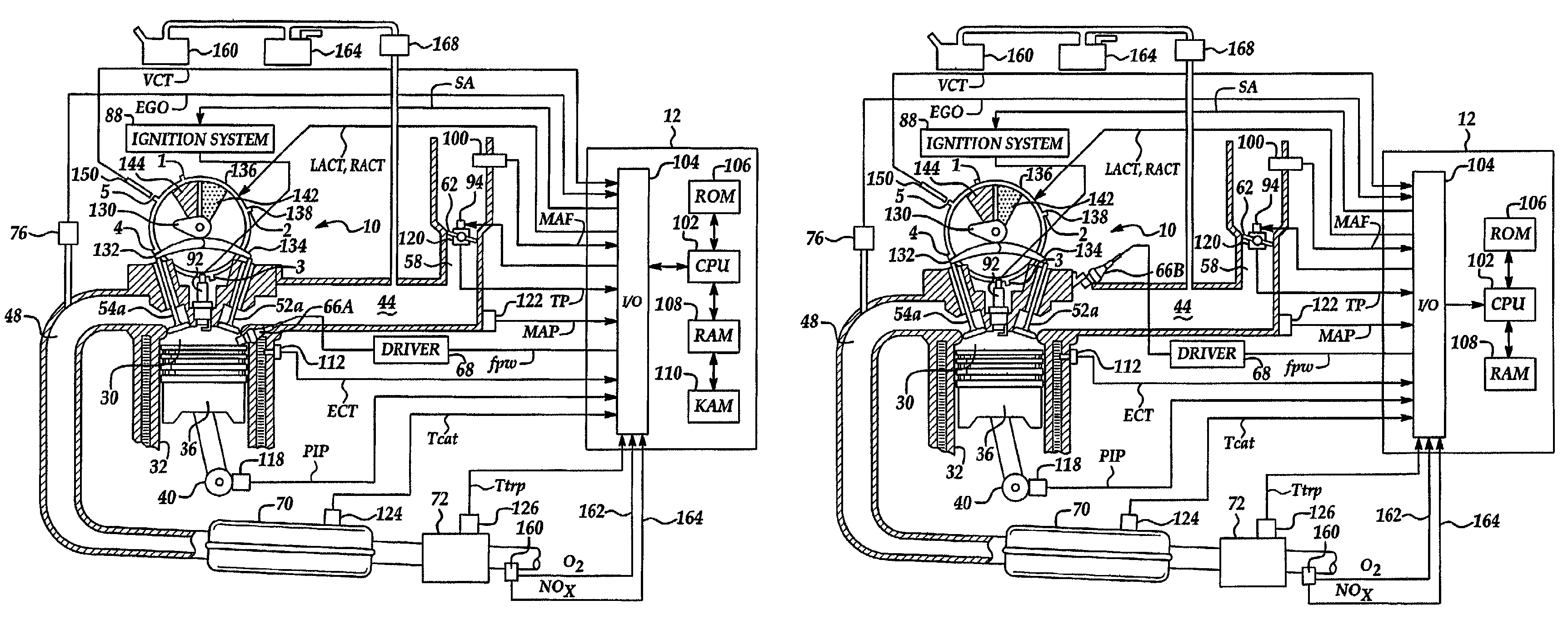
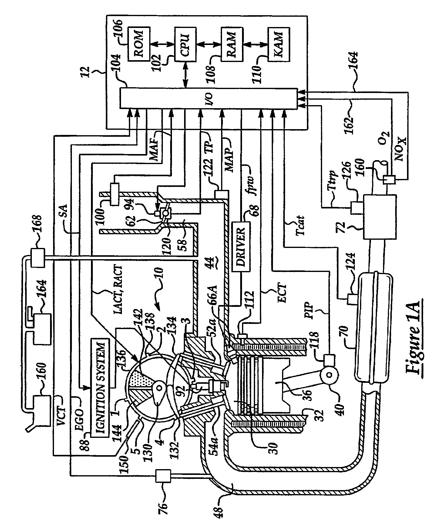
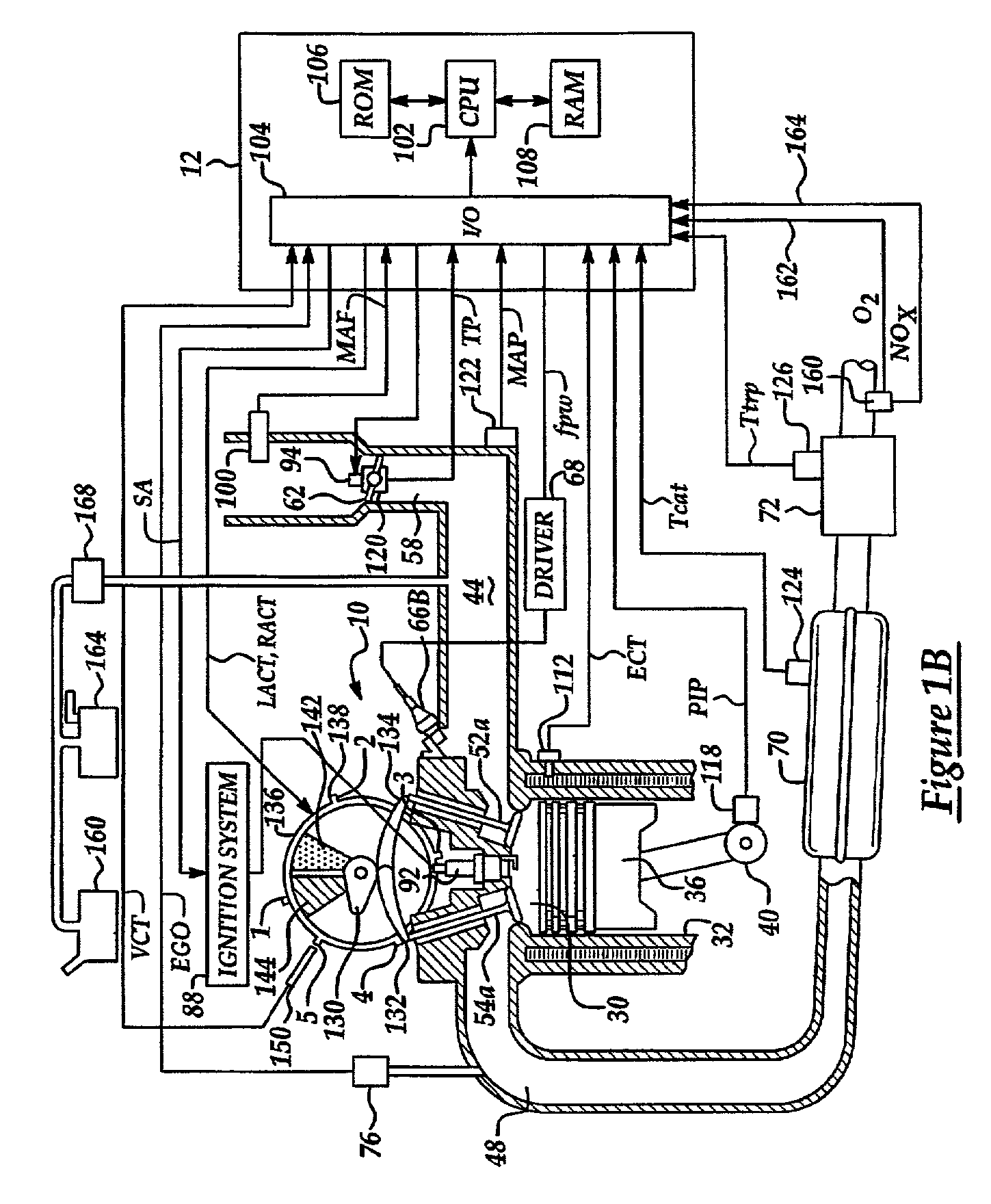
[0045]FIGS. 1A and 1B show one cylinder of a multi-cylinder engine, as well as the intake and exhaust path connected to that cylinder. As described later herein with particular reference to FIG. 2, there are various configurations of the cylinders and exhaust system.

[0046]Continuing with FIG. 1A, direct injection spark ignited internal combustion engine 10, comprising a plurality of combustion chambers, is controlled by electronic engine controller 12. Combustion chamber 30 of engine 10 is shown including combustion chamber walls 32 with piston 36 positioned therein and connected to crankshaft 40. A starter motor (not shown) is coupled to crankshaft 40 via a flywheel (not shown). In this particular example, piston 36 includes a recess or bowl (not shown) to help in forming stratified charges of air and fuel. Combustion chamber, or cylinder, 30 is shown communicating with intake manifold 44 and exhaust manifold 48 via respective intake valves 52a and 52b (not shown), and exhaust valv...


PUM


Abstract

A method is disclosed for controlling operation of an engine coupled to an exhaust treatment catalyst. Under predetermined conditions, the method operates an engine with a first group of cylinders combusting a lean air / fuel mixture and a second group of cylinders pumping air only (i.e., without fuel injection). In addition, the engine control method also provides the following features in combination with the above-described split air / lean mode: idle speed control, sensor diagnostics, air / fuel ratio control, adaptive learning, fuel vapor purging, catalyst temperature estimation, default operation, and exhaust gas and emission control device temperature control. In addition, the engine control method also changes to combusting in all cylinders under preselected operating conditions such as fuel vapor purging, manifold vacuum control, and purging of stored oxidants in an emission control device.

Description

BACKGROUND OF INVENTION[0001]1. Field of the Invention[0002]The present invention relates to control strategies for engines, and more particularly, to control strategies for rapidly heating an emission control device.[0003]2. Background of the Invention[0004]Emission control devices, such as catalytic converters, can reduce emissions generated by engine combustion. However, the effectiveness of such emission control devices varies with operating temperature. For example, the efficiency of an emission control device may be much greater at higher temperatures than it is at lower temperature. Typically, a “light-off” temperature is used to signify a certain temperature above which a prescribed efficiency is achieved.[0005]In vehicle emission control systems, measures are taken to rapidly heat emission control devices after starting of a vehicle, so that tail pipe emissions can be minimized. In particular, as described in U.S. Pat. No. 5,497,745, an ignition timing signal is retarded du...

Claims


Application Information

Patent Timeline
IPC IPC(8): F01N3/00F01N3/20F01N11/00F01N13/02F01N13/04F01N13/10F02D37/02F02D41/02F02D41/06F02P5/15
CPCF01N3/2006F01N13/011F02D41/025F02P5/1506F02P5/1512F01N13/009F01N13/107F01N2430/02F01N2430/06F01N2430/08F01N2560/026F02D37/02F02D41/0255F02D41/064Y02T10/46Y02T10/26F01N11/007Y02T10/12Y02T10/40
Inventor INGRAM, GRANT ALANSURNILLA, GOPICHANDRA
Owner FORD GLOBAL TECH LLC
Learn More