Method of manufacturing yoke of rotary electric machine
a technology of rotary electric machines and yoke, which is applied in the manufacture of stator/rotor bodies, magnetic bodies, magnetic circuit shapes/forms/construction, etc., can solve the problems of reducing the service life of the yoke, the inability of a rotary electric machine to manufacture yoke, and the inability to weld the opposite sides with expensive laser beams, so as to prevent the effect of shear drop
- Summary
- Abstract
- Description
- Claims
- Application Information
AI Technical Summary
Benefits of technology
Problems solved by technology
Method used
Image
Examples
first embodiment
[0064]A method of manufacturing a stator yoke of a starter motor according to the invention is described hereafter. The method of manufacturing a yoke includes steps of cutting, fitting and clamping.
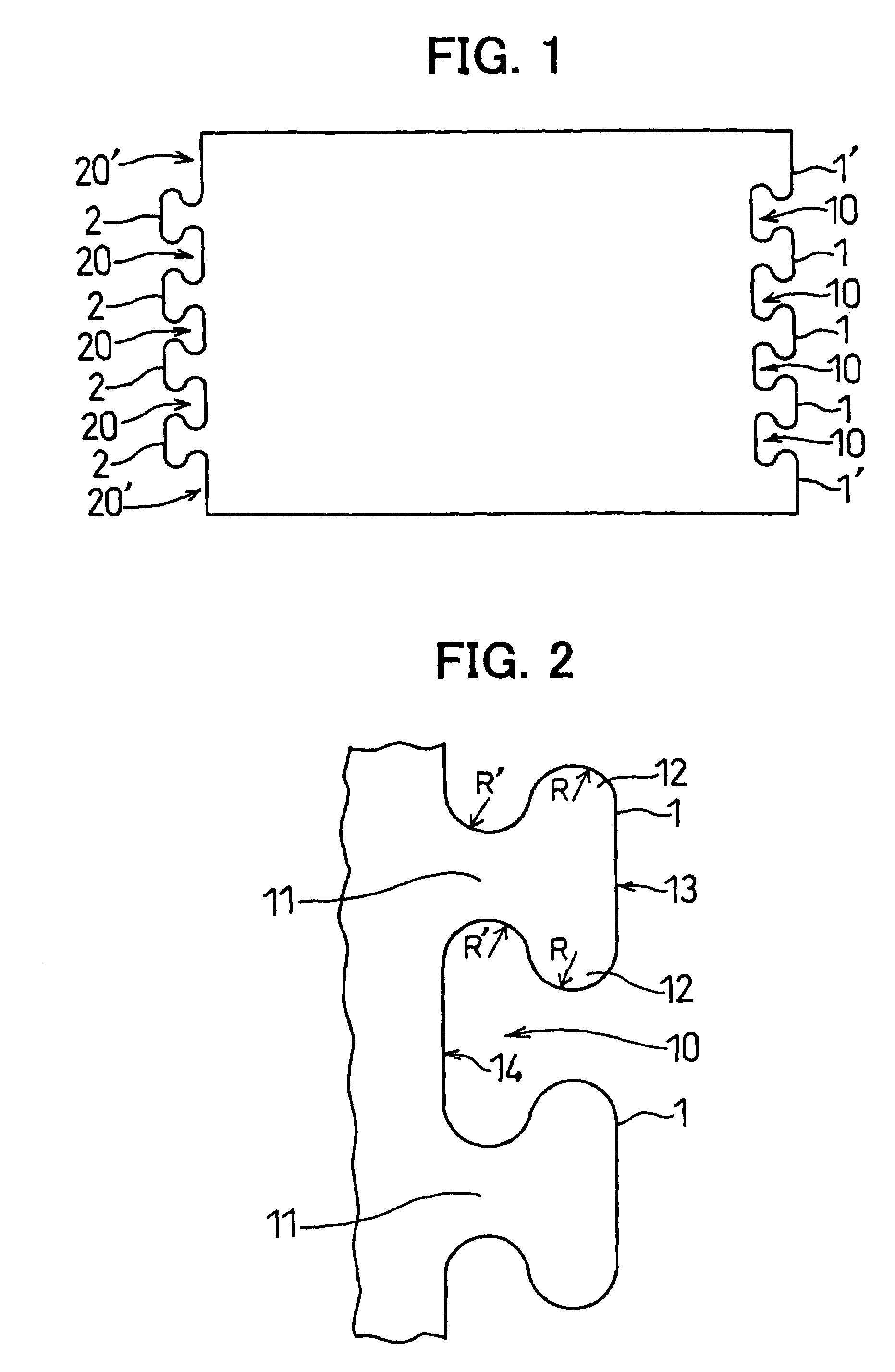
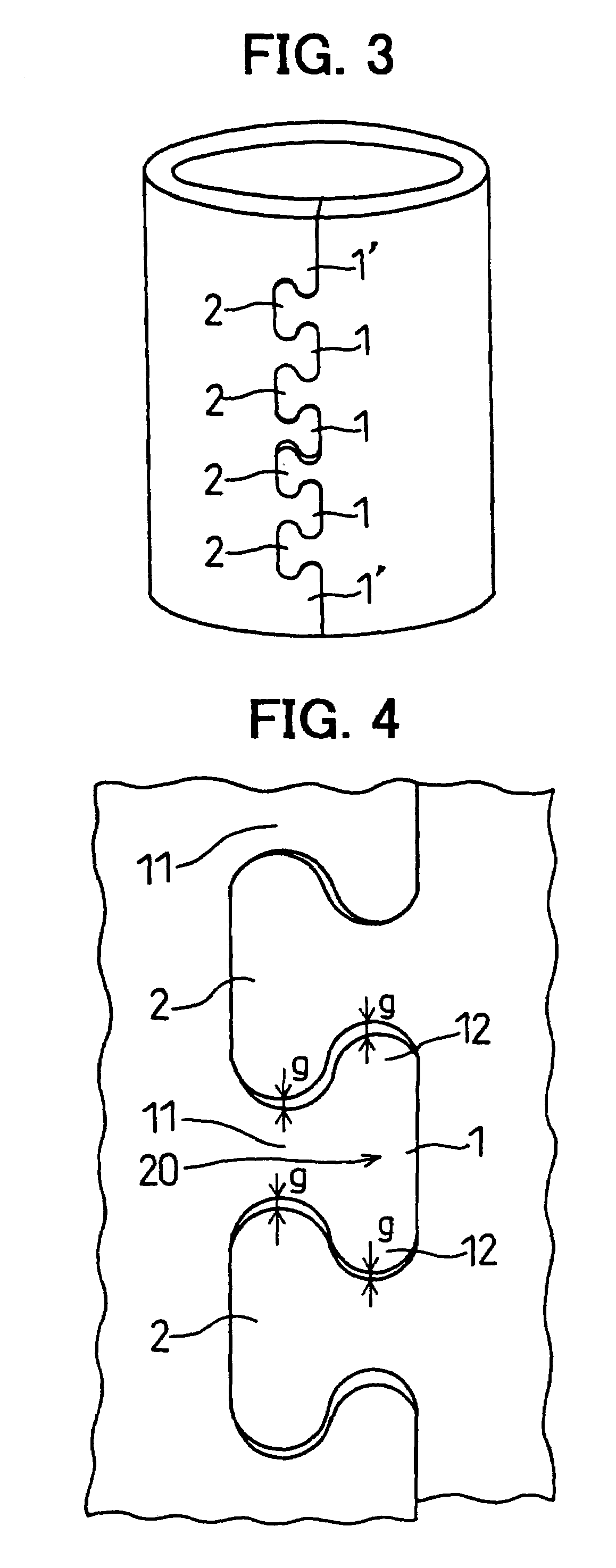
[0065]At the cutting step, a belt like long steel sheet is cut into a rectangular shape having first dovetail convexities 1 on one side thereof and second dovetail convexities 2 on the other side so that they can be fitted to the first dovetail convexities. A press cutter is used to cut the steel sheet in the following manner to have a good yield rate: when the first dovetail convexities 1 are cut at one side, the second dovetail convexities 2 are automatically formed at the other side, as the fragments of the first dovetail convexities.
[0066]As shown in FIG. 1, there are three first dovetail convexities 1 formed at the middle and half-dovetail fragments 1′ and straight portions at the opposite axial ends, on one side (right in FIG. 1) of the cut steel sheet. There are four concavities 1...
second embodiment
[0082]A method of manufacturing a yoke according to the invention is described hereafter.
[0083]If the dovetail convexities 1 and 2 formed near the axial edges are punched, the incomplete dovetail convexities 1′ may deform in the axial direction, and a gap G is formed between one and the other sides of the steel sheet at the axial ends of the yoke Y as shown in FIG. 12.
[0084]In the method according to the second embodiment, the portions at axially opposite ends of the first and second dovetail convexities 1 and 2 are not punched, as shown in FIG. 13. That is, the portion along the border of the incomplete dovetail 1′ and the second dovetail 2 is not punched in the clamping step. Others are the same as the embodiment 1.
[0085]Therefore, the incomplete dovetail convexities 1′ fitted to the dovetail convexities 2 at the axial ends of the yoke Y without deforming, so that the clamped portion is not separated. Further, the number of portions being punched in the clamping step can be reduce...
fourth embodiment
[0091]A method of manufacturing a yoke is described with reference to FIGS. 15–21.
[0092]The method of manufacturing a yoke according to this embodiment has a tube-forming step and a pre-heating step and a painting step in this order, as described in detail below.
[0093]The tube-forming step includes a cutting step and a clamping step.
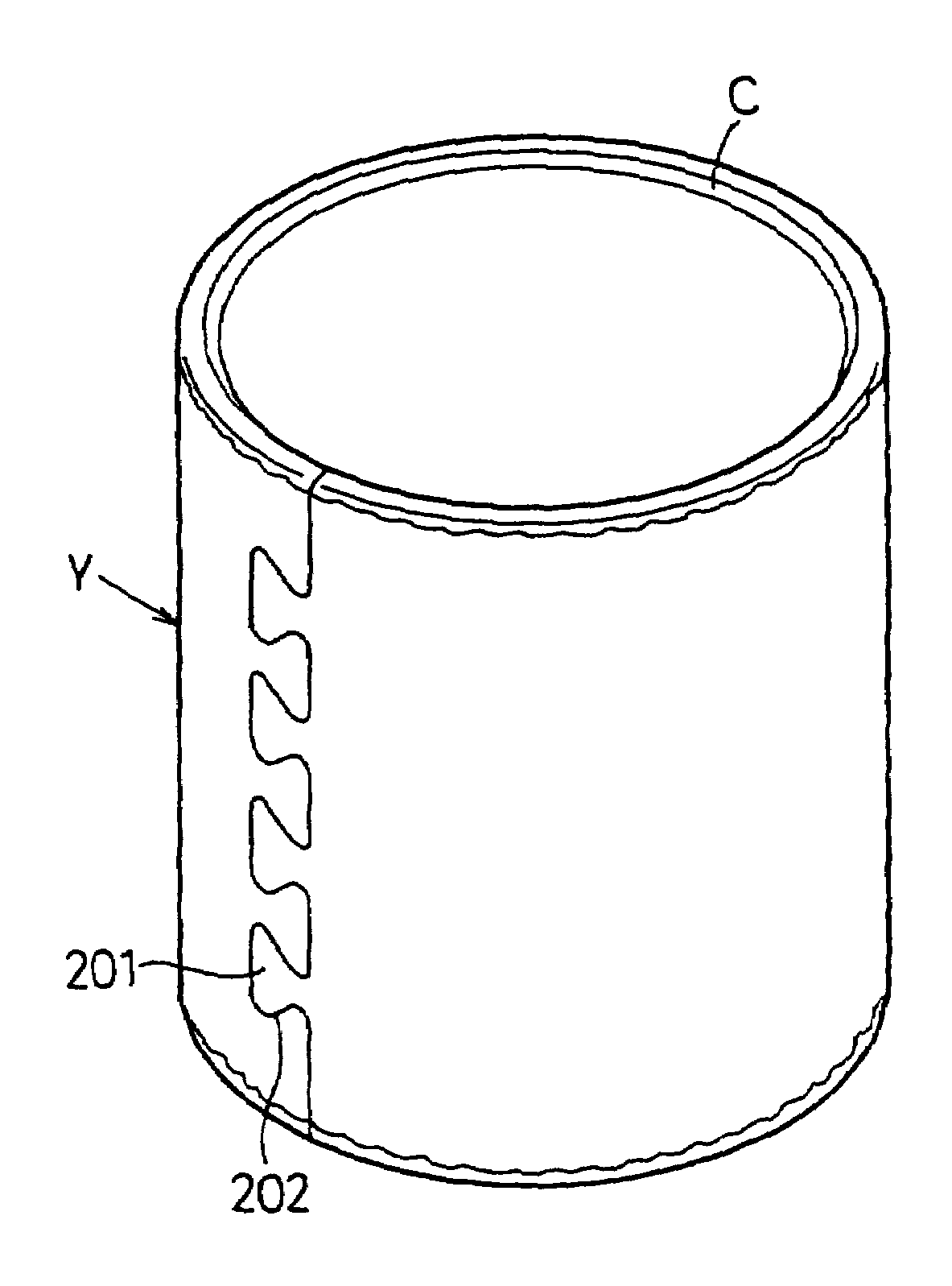
[0094]In the cutting step, a belt-like long plate is cut by a press machine or a press cutter into a rectangular sheet to form a plurality of convexities 101 at one side and a plurality of concavities 102 to be fitted to the convexities 101 at the other side. When the convexities 101 are formed at one side, the concavities 102 are automatically formed at the other end.
[0095]The one side of the cut sheet (upper side of FIG. 15) has three convexities 101 at the middle thereof, and the other side of the cut sheet (lower side of FIG. 15) has three concavities 102 at the middle thereof.
[0096]The three convexities 101 and the three concavities 102 are complem...
PUM
| Property | Measurement | Unit |
|---|---|---|
| cylindrical shape | aaaaa | aaaaa |
| thickness | aaaaa | aaaaa |
| trapezoidal shape | aaaaa | aaaaa |
Abstract
Description
Claims
Application Information
 - R&D
- Intellectual Property
- Life Sciences
- Materials
- Tech Scout
- Unparalleled Data Quality
- Higher Quality Content
- 60% Fewer Hallucinations
Browse by: Latest US Patents, China's latest patents, Technical Efficacy Thesaurus, Application Domain, Technology Topic, Popular Technical Reports.
© 2025 PatSnap. All rights reserved.Legal|Privacy policy|Modern Slavery Act Transparency Statement|Sitemap|About US| Contact US: help@patsnap.com


