Motor torque control apparatus and method for automotive vehicle
a technology of motor torque and control apparatus, which is applied in the direction of electric controllers, dynamo-electric converter control, gearing, etc., can solve the problem of inability to achieve the desired acceleration or deceleration of the vehicl
- Summary
- Abstract
- Description
- Claims
- Application Information
AI Technical Summary
Benefits of technology
Problems solved by technology
Method used
Image
Examples
first embodiment
[0051]the motor torque control apparatus according to the present invention will now be explained with reference to FIG. 5.
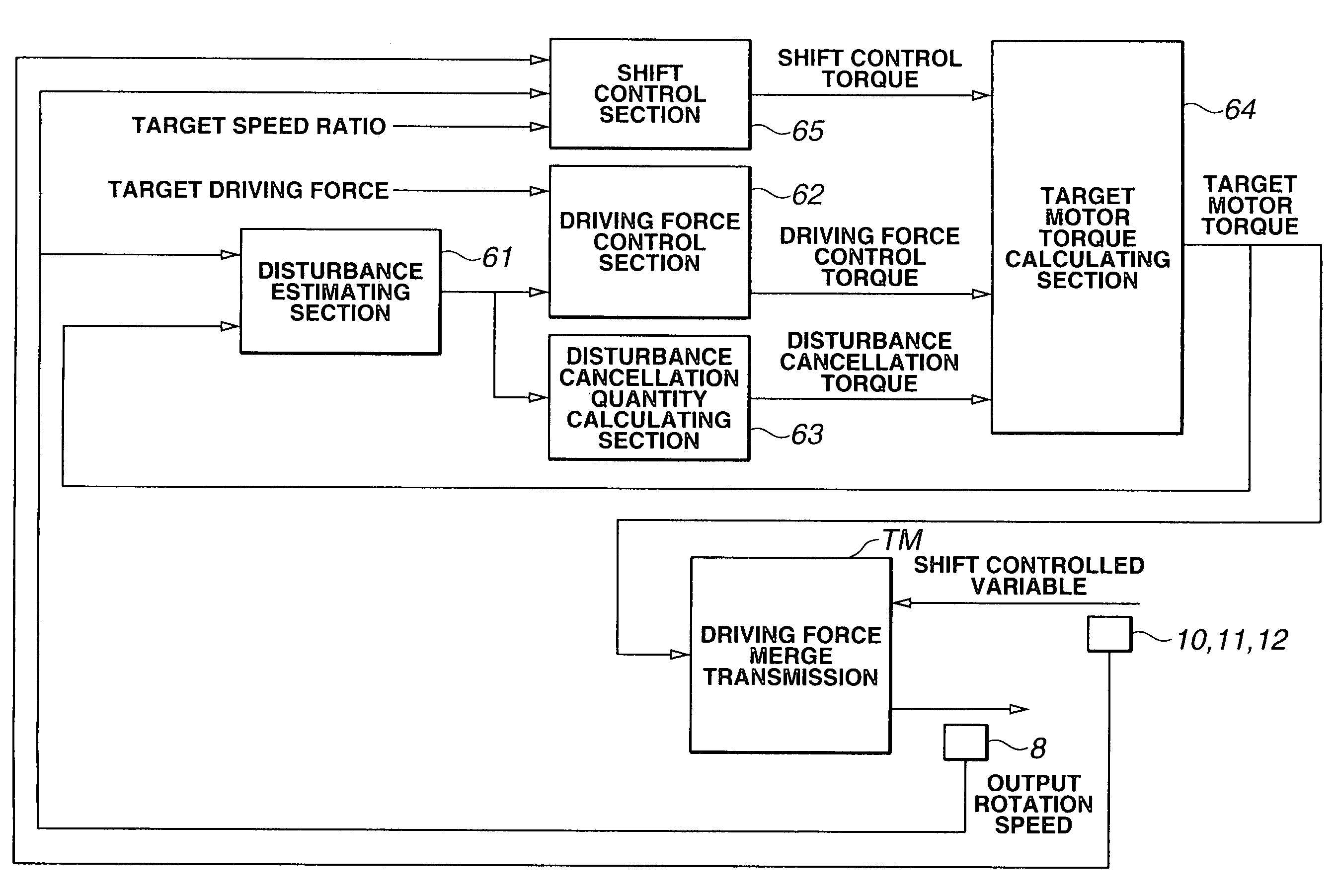
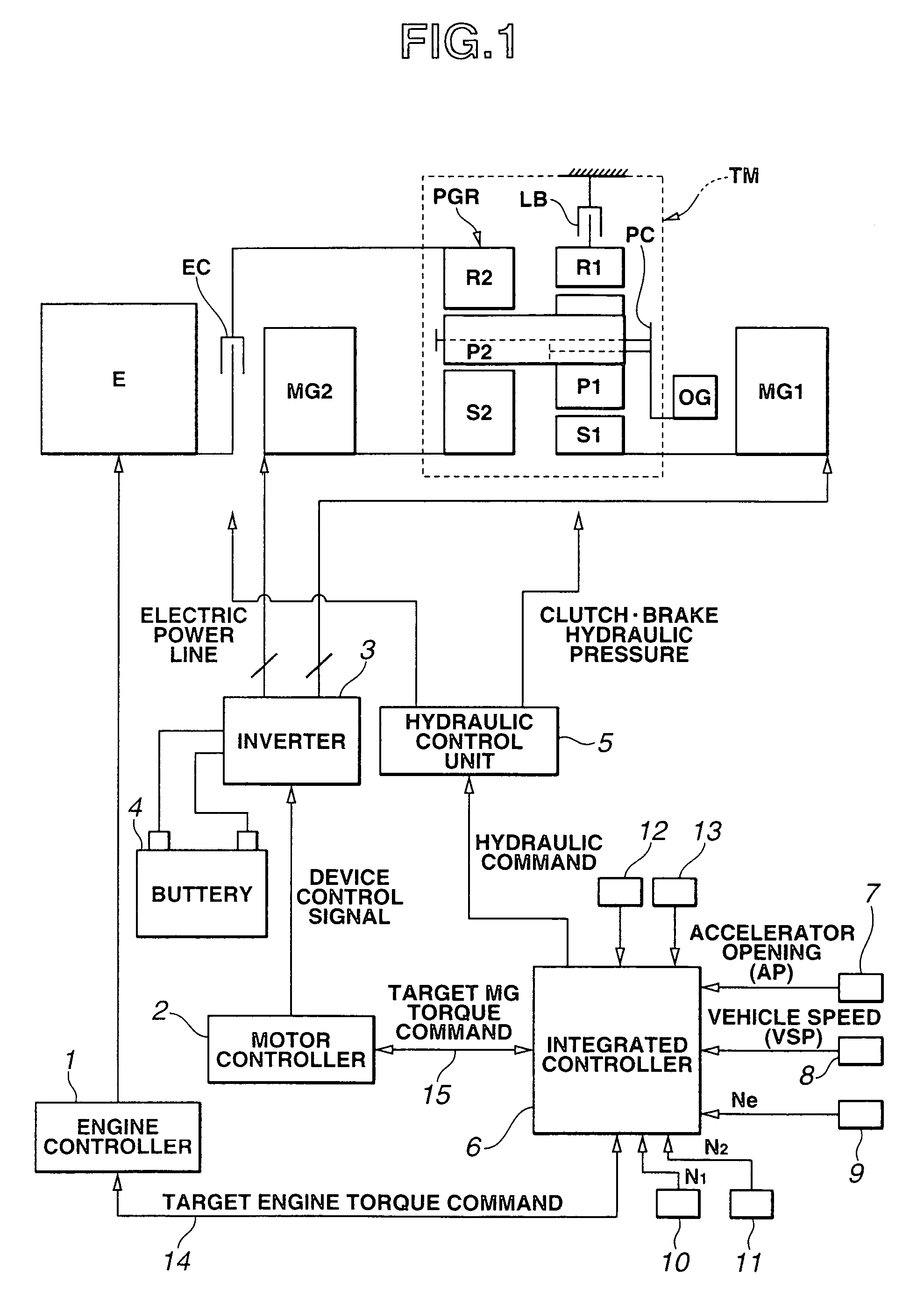
[0052]In the motor torque control apparatus of the first embodiment, a disturbance observer estimates the driving force and then the estimated driving force is brought closer to a target value by way of servo control. The motor torque control apparatus of this embodiment (or, a controller composed of the disturbance observer and a motor torque control section of this embodiment) includes accelerator opening sensor 7, vehicle speed sensor 8 (corresponding to an output-shaft rotation speed sensing section (or, means)), a disturbance estimating section (or, means) 61, a driving force control section (or, means) 62, a disturbance cancellation quantity calculating section (or, means) 63, and a target motor torque calculating section (or, means) 64.
[0053]Vehicle speed sensor 8 senses an output-shaft (or, output-axis) rotation speed of hybrid transmission (i.e., drivin...
second embodiment
[0092]the motor torque control apparatus according to the present invention will now be explained with reference to FIG. 8.
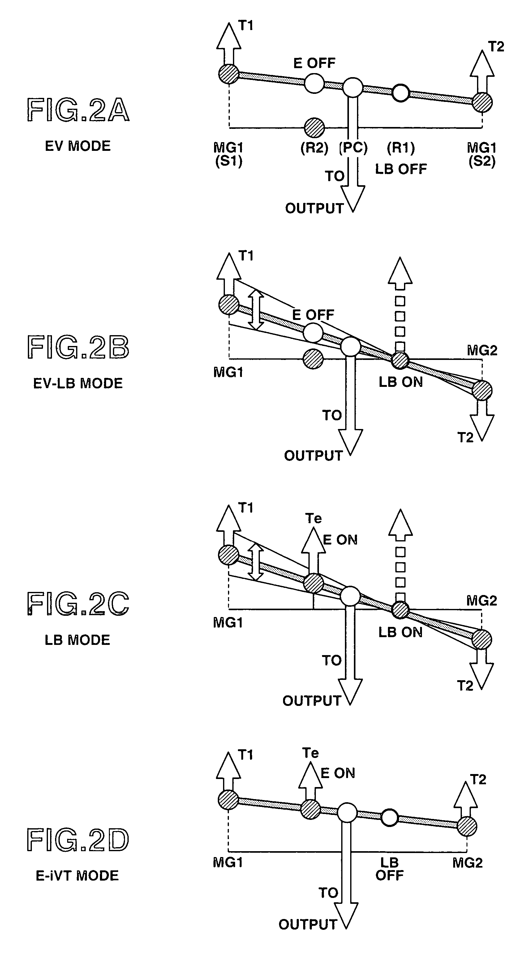
[0093]The second embodiment is an example which performs the speed ratio control and the driving force control (motor torque control), in the case of “EV mode” or “E-iVT mode” where low brake LB is open.
[0094]Namely, in the motor torque control apparatus of the second embodiment, the disturbance observer estimates the driving force, and then the driving force control torque is so calculated as to eliminate the difference between the estimated driving force and a target value (target driving force). Moreover, a shift (or, speed ratio) control torque is so calculated as to reduce the difference between an actual speed ratio and a target speed ratio. The motor torque is controlled or adjusted, in such a manner that this driving force control torque is only used for variation in acceleration / deceleration of the output shaft's rotation, and this shift control torque ...
third embodiment
[0118]the motor torque control apparatus according to the present invention will now be explained with reference to FIG. 9.
[0119]In the motor torque control apparatus of the third embodiment, a disturbance observer estimates the running resistance torque (i.e., torque according to the running resistance) and the torsional torque of the drive shaft (wheel shaft), and then the target driving force is achieved by the disturbance observer. The motor torque control apparatus of this embodiment (or, the controller of the motor torque control apparatus in this embodiment) includes accelerator opening sensor 7, vehicle speed sensor 8 (corresponding to the output-shaft rotation speed sensing section (or, means)), a wheel speed sensor 13 (corresponding to a wheel rotation speed sensing section (or, means)), a disturbance estimating section (or, means) 161, a target acceleration calculating section (or, means) 162, a disturbance cancellation quantity calculating section (or, means) 163, and a ...
PUM
 Abstract
Description
Claims
Application Information
 - R&D
- Intellectual Property
- Life Sciences
- Materials
- Tech Scout
- Unparalleled Data Quality
- Higher Quality Content
- 60% Fewer Hallucinations
Browse by: Latest US Patents, China's latest patents, Technical Efficacy Thesaurus, Application Domain, Technology Topic, Popular Technical Reports.
© 2025 PatSnap. All rights reserved.Legal|Privacy policy|Modern Slavery Act Transparency Statement|Sitemap|About US| Contact US: help@patsnap.com


