Starter unit

a starter unit and multi-functional technology, applied in the direction of fluid couplings, gearings, couplings, etc., can solve the problems of increased slippage, low service life of the starter element, and the coupling device is then subject to increased wear, so as to achieve low design and control technology effort, low overall length, and easy integration into the drive system

Inactive Publication Date: 2007-01-09
VOITH PATENT GMBH
View PDF19 Cites 3 Cited by
  • Summary
  • Abstract
  • Description
  • Claims
  • Application Information

AI Technical Summary

Benefits of technology

[0005]The object of the invention is therefore to improve a starter unit for use in change-speed gearbox components, to make it suitable for use in automated change-speed gearboxes in drive systems, while avoiding the above disadvantages. In particular, in doing so, a starting process that is as free from wear as possible is realized, regardless of the duration of the state of increased slip. At the same time, the starter unit itself should have low design and control technology effort and be easily integrated into the drive system or into a power transmission unit, for example in the form of a physical gearbox unit, whereby the ever increasing requirements for a low overall length should be taken into account. A further aspect of the invention comprises enabling interruption of the power flow during the gear-shifting process.
[0009]The foregoing provides an almost wear-free starting process and has the advantages that the hydrodynamic component does not have to be drained during the gear-shifting process that no additional clutch mechanism is required for interrupting the power. The decoupling of the input, which as a rule forms the input shaft of the gearbox, from the subsequent gear stages is done solely by the free wheel mechanism, which thus safeguards the function of the synchronizing device in the change-speed gearbox.
[0018]A starter unit according to the invention may be made very small and thus only has a small effect on the overall length when integrated into a physical gearbox unit, in particular an automated change-speed gearbox. The constructional unit comprised of the hydrodynamic coupling or converter, bypass clutch and free wheel mechanism can be offered and supplied by the trade as a pre-fitted modular component. Integration into a connecting unit then takes place in a positively locked and / or flush manner, for example by fitting the modular component to an input shaft of the connecting element, in particular of a physical gearbox unit, or by a shaft to collar connection between the output of the starter unit and the input of the connecting unit, whereby the input shaft of the connecting unit can simultaneously form the output shaft of the starter unit in the assembled state.
[0019]When the bypass clutch is a mechanical clutch with a disk construction in the form of a wet multiple disk clutch, there are a large number of possibilities for realizing the wet running of the multiple disks. This is preferably realized in a simple manner by simultaneously using the operating medium, which is situated outside the working area of the hydrodynamic coupling, as a lubricant for the bypass clutch. As a rule, this is the operating medium, which collects in the operating medium sump of the coupling housing or in a coupling tray or a storage chamber. In this case, additional sealing measures between the hydrodynamic coupling and the bypass clutch can be dispensed with, and the bypass clutch can easily be integrated into the housing of the hydrodynamic coupling. This embodiment enables design of a wear-free starter unit, which is particularly compact with regard to construction and functionality. These comments can also be applied to the converter.
[0020]In a further aspect of the invention, providing a device for optionally fixing the turbine wheel enables operating the hydrodynamic coupling simultaneously as a fully functional hydrodynamic retarder and thus enables producing a wear-free braking device. A separate hydrodynamic braking device, which is used especially in commercial vehicles, can be dispensed with. Ventilation losses of the retarder are very low in comparison with the conventional retarder. The device for fixing or coupling the turbine wheel to the housing, in the simplest case, is designed as a braking device, preferably with a disk construction. This acts on the driven element of the hydrodynamic coupling, i.e. on the turbine wheel. The connection of the braking element to the turbine wheel takes place between the turbine wheel and the free wheel mechanism. In a particularly advantageous manner, the vehicle can be prevented from rolling backward on inclines when the gear is engaged and the braking element is closed.
[0028]The combination of a hydrodynamic coupling or a hydrodynamic converter, a bypass clutch and, possibly, in addition a torsional oscillation damper, and the integration into a modular component, provides the possibility of creating a multifunctional drive component with a low overall space requirement. In doing so, these elements can be integrated into a common housing. It is possible for the modular component to be offered independently as a saleable component. At the same time, the housing of the hydrodynamic coupling can be used as a common housing.

Problems solved by technology

However, use of a friction clutch as a starter element caused problems during operation, characterized by increased slip over a longer time period.
Due to the enormous thermal loading, the coupling device is then subjected to increased wear.
Furthermore, the appearance of wear causes low service life for the starter element.
The disadvantage of using starter elements in the form of hydrodynamic converters consists of the high costs for the hydrodynamic part and the requirement to provide a clutch mechanism.
However, it has the disadvantage for automatic change-speed gearboxes, in which the engine or turbine experiences a considerable change of speed during the gear-shifting process, during which the speed of the turbine wheel has to be synchronized.

Method used


Image

  • Starter unit
  • Starter unit
  • Starter unit

Examples


Embodiment Construction

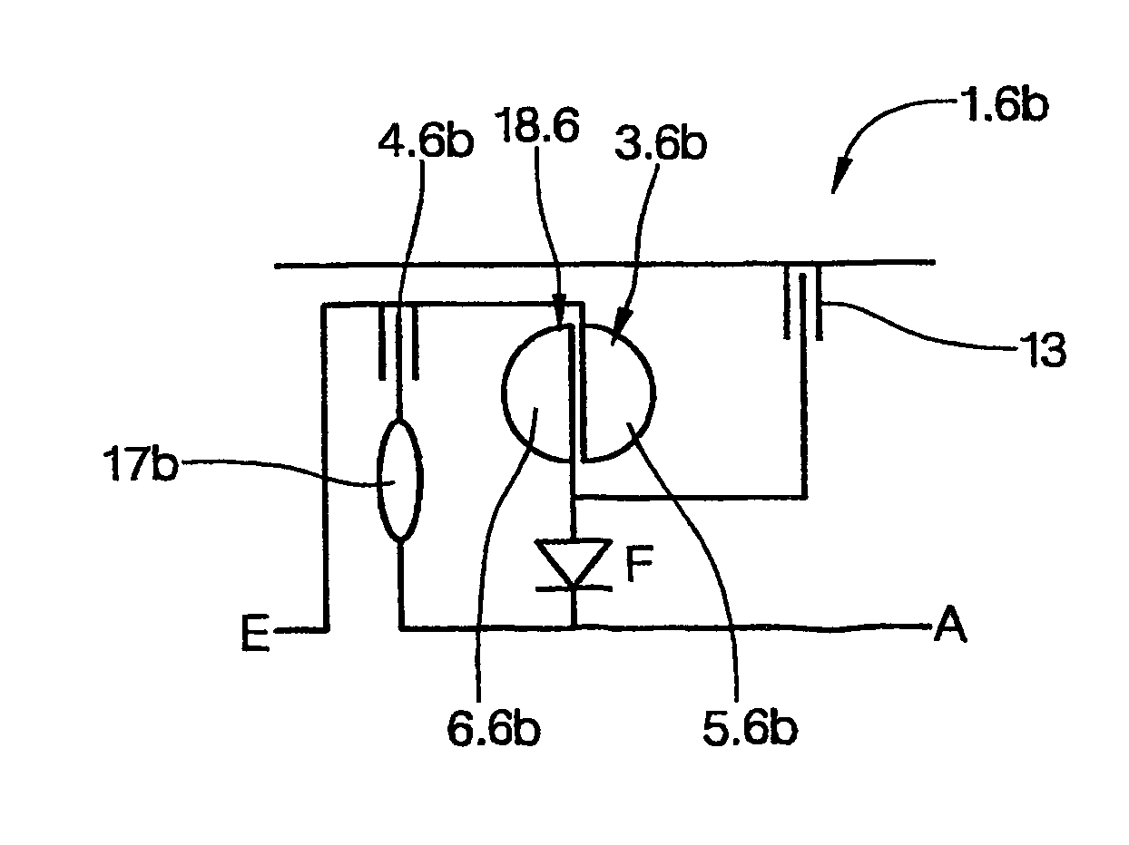
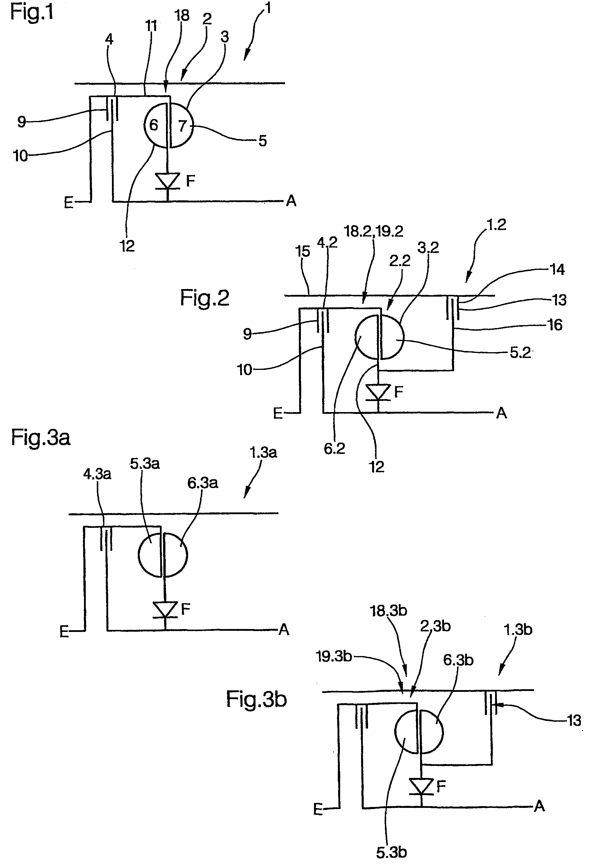
[0037]FIG. 1 is a schematic simplified representation of the basic construction of a starter unit 1 according to the invention, comprising a starter element 2. The starter unit 1 comprises a hydrodynamic component 18 in the form of a hydrodynamic coupling 3 and a bypass clutch 4. The hydrodynamic coupling 3 and the bypass clutch 4 are connected in parallel. The hydrodynamic coupling 3 comprises at least one primary wheel acting as a pump wheel 5 and a secondary wheel acting as a turbine wheel 6, which together form a toroidal working area 7. The bypass clutch 4 can be designed in one of many ways, but preferably in the form of a disk clutch, in particular a multiple disk clutch. This comprises a clutch input disk 9 and a clutch output disk 10, which can be brought into at least indirect active frictional contact with one another, i.e. either directly or via further disk-shaped intermediate elements, which form frictional pairs with one another. Furthermore, the starter unit 1 compri...


PUM


Abstract

A starter unit comprising: an input and an output; a starter element, configured as a hydrodynamic component comprising a drive element that can be coupled to the input in a rotationally fixed manner and a driven element that can be coupled to the output. A free wheel mechanism is located between the driven element of the starter element and the output.

Description

BACKGROUND OF THE INVENTION[0001]The invention relates to a multifunctional unit, particularly a starter unit for use in change-speed gearboxes, and particularly automatic and automated change-speed gearboxes, and it further relates to a change-speed gearbox, in particular an automated change-speed gearbox and to a vehicle with a change-speed gearbox.[0002]Gearboxes for use in vehicles, in particular commercial vehicles, in the form of change-speed gearboxes or automated change-speed gearboxes are known in a large number of different embodiments. The starting process is usually realized using a coupling device in the form of a friction clutch or a hydrodynamic converter. However, use of a friction clutch as a starter element caused problems during operation, characterized by increased slip over a longer time period. This applies especially to the starting process. Due to the enormous thermal loading, the coupling device is then subjected to increased wear. In order to keep this wear...

Claims


Application Information

Patent Timeline
Patent Type & Authority Patents(United States)
IPC IPC(8): F16D33/00F16F15/12F16H41/24F16H45/00F16H45/02
CPCF16D33/00F16H45/00F16H45/02F16H2045/005F16H2041/246
Inventor BECKE, MARTINNITSCHE, MARTIN
Owner VOITH PATENT GMBH
Why Eureka
Try Eureka