Eureka AIR delivers breakthrough ideas for toughest innovation challenges, trusted by R&D personnel around the world.

Signal derived bias supply for electrostatic loudspeakers

a technology of electrostatic speakers and power supplies, applied in the field of electrostatic speakers, can solve the problems of inconvenient wiring, inconvenient installation, and inability to bias the speaker, and achieve the effect of reducing the cost of self-biasing

Inactive Publication Date: 2007-01-02
TURTLE BEACH
View PDF9 Cites 9 Cited by
  • Summary
  • Abstract
  • Description
  • Claims
  • Application Information

AI Technical Summary

Benefits of technology

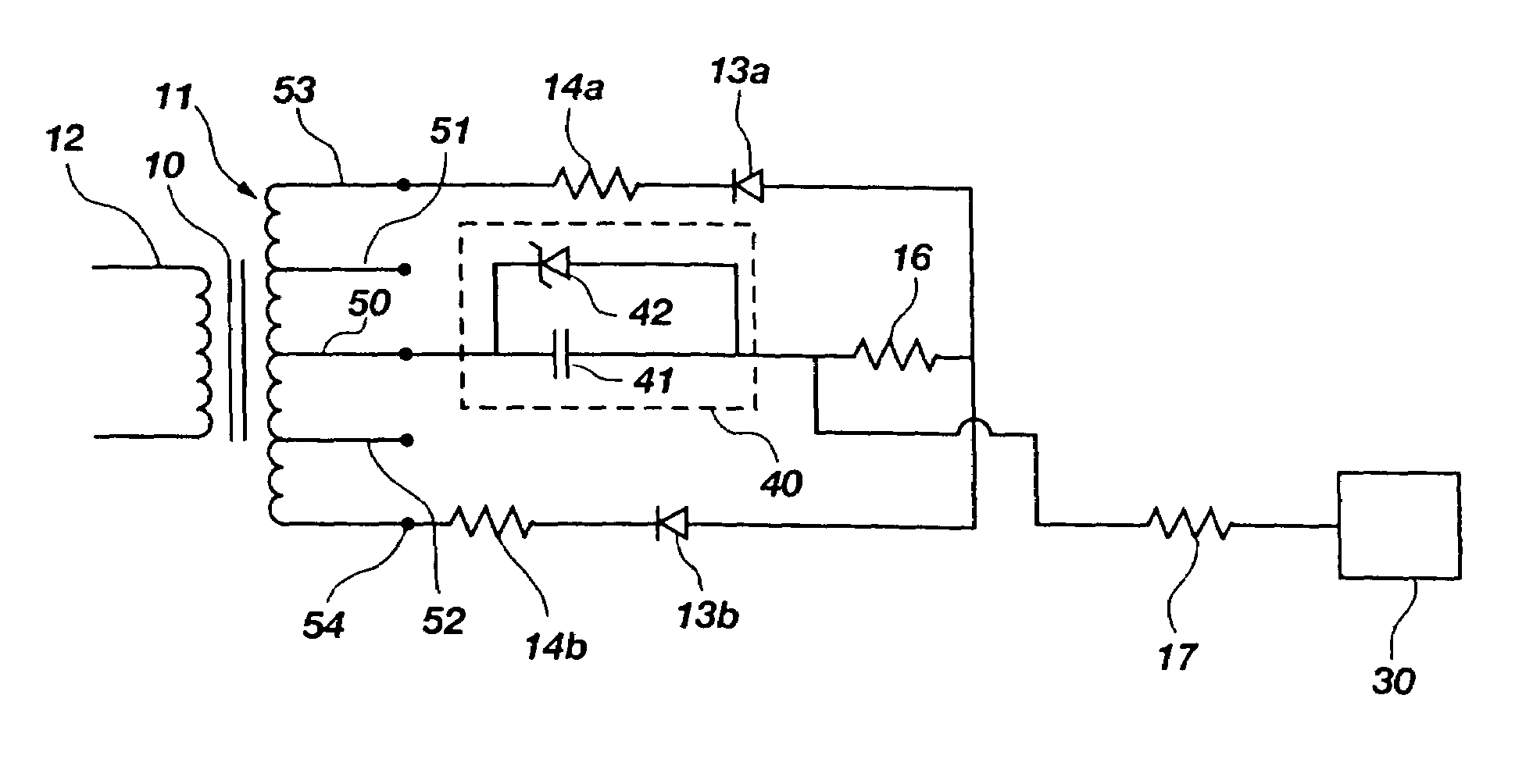
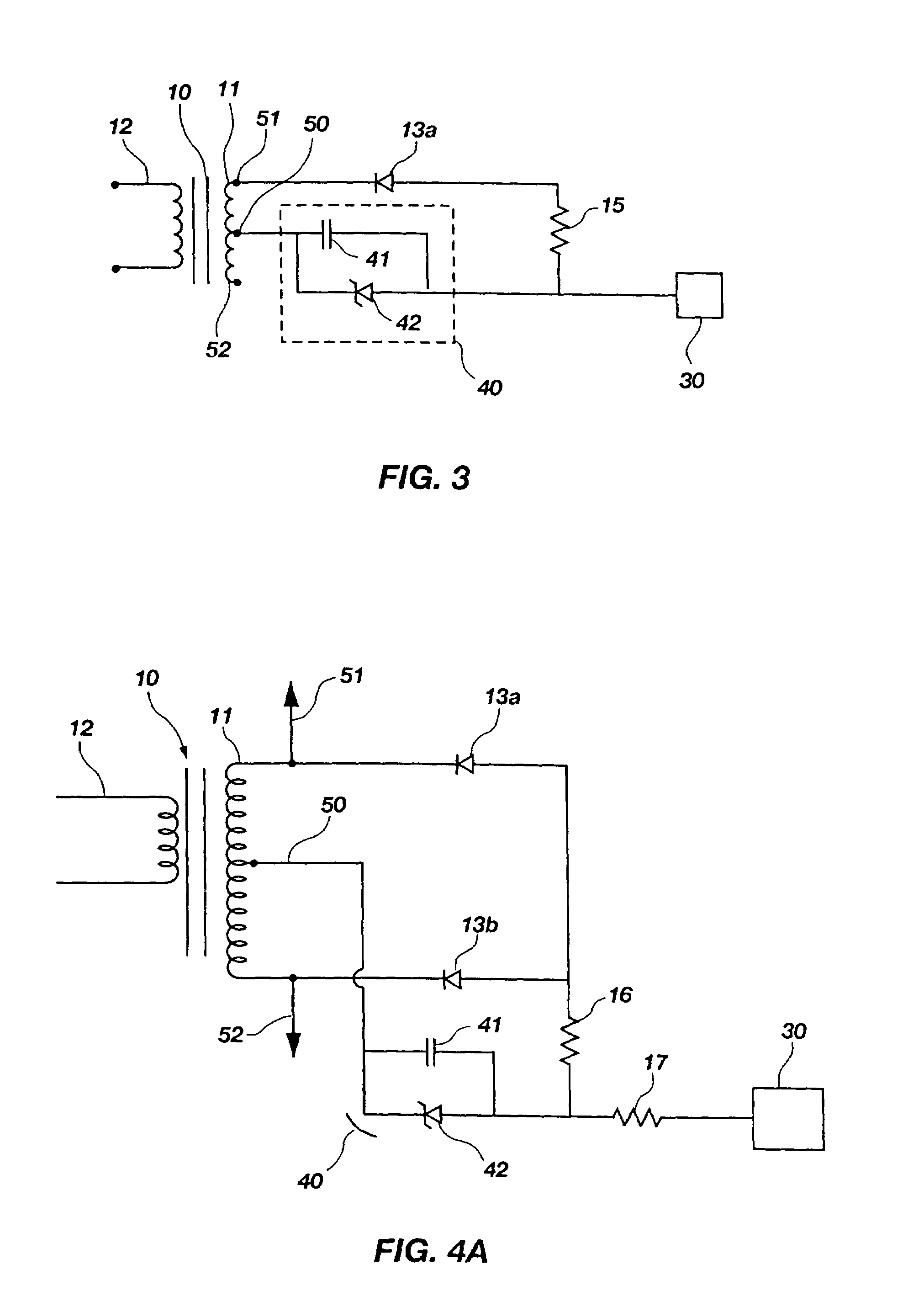
[0012]It is an object of the present invention to provide a bias system which uses a simple two wire speaker connection and the reduces cost of self-biasing for DC field generation in the electrostatic speaker.
[0016]It is an additional object of the invention to provide a more effective startup using greater multiplication stages in the voltage multiplier circuit and a separate charging signal delivered from the associated active electronics which charges on startup, periodically, or on a steady basis.

Problems solved by technology

This configuration is easy to implement but can be somewhat costly.
It can also be inconvenient to have to run separate AC main wires and also signal wires from the power amplifier.
Another drawback of using a separate AC power supply is that the separate power supply results in additional cost and wiring which makes electrostatic speakers a less desirable choice in most consumer applications.
Thus, the electrostatic speakers are less desirable even though they offer superior performance and greater sound fidelity when they couple into the air.
In particular applications where the systems run off of DC, such as a laptop computer or a portable music system, a high voltage source of AC may not be available.
First, because the AC audio signal is not predictable or repeatable, the voltage available at the output of the audio signal step-up transformer can vary from a zero voltage to a voltage that can damage the electrostatic unit due to over voltage.
A second problem with the prior art type of bias system is that when the audio equipment is first powered up, the self-bias voltage (and hence the resulting electric field) is at, or close to zero.
To increase the signal rise time, the transformer step-up ratio can be increased but this can then make the first problem of over-voltage even worse.
A third problem is that prior art self-bias circuits provide a variable bias voltage.
A fourth problem with this type of bias system is that in a multi-channel system, each channel can end up with different bias levels at any given time.
Therefore, each channel would have a different efficiency and would be mismatched depending on how well the multi-channel program material was matched from channel to channel at any given moment.

Method used


Image

  • Signal derived bias supply for electrostatic loudspeakers
  • Signal derived bias supply for electrostatic loudspeakers
  • Signal derived bias supply for electrostatic loudspeakers

Examples


Embodiment Construction

[0031]Reference will now be made to the drawings in which the various elements of the present invention will be given numerical designations and in which the invention will be discussed so as to enable one skilled in the art to make and use the invention. It is to be understood that the following description is only exemplary of certain embodiments of the present invention, and should not be viewed as narrowing the claims which follow.

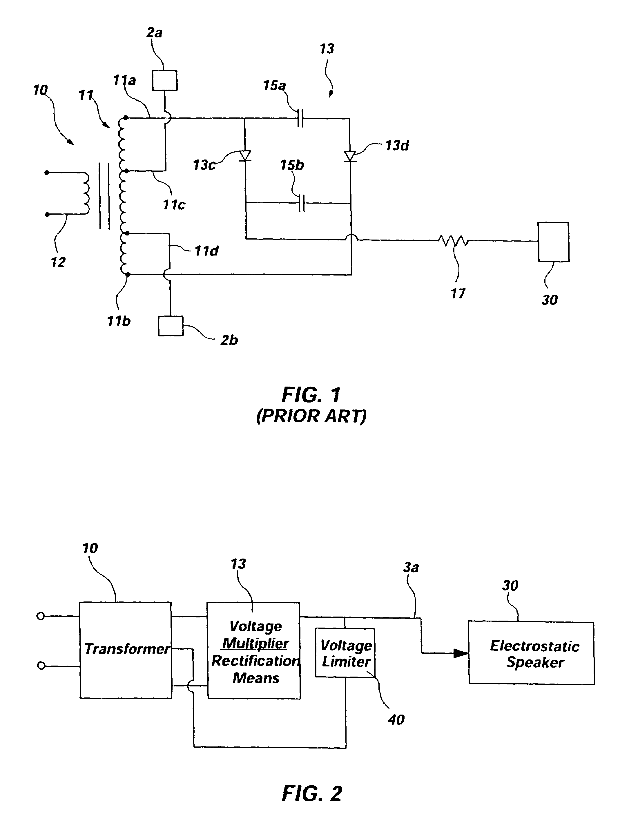
[0032]FIG. 1 represents a prior art self bias circuit for an electrostatic speaker. The transformer 10 accepts an input signal to a primary winding 12, which is then converted into a higher voltage and output through the secondary winding 11. Lower voltage outputs 11c and 11d send audio signals to stators 2a and 2b. Higher voltage taps 11a and 11b feed the voltage doubler 13, which consists of diodes 13c and 13d, and capacitors 15a and 15b. The unregulated, non-limited voltage signal is sent through resistor 17 to diaphragm 30. With this type of system...


PUM


Abstract

An electrostatic loudspeaker requires a high voltage DC bias power supply to bias the stators and diaphragms of electrostatic speakers. A self biased power supply eliminates the need for an external power supply by deriving a high voltage bias from the stator AC signal voltages which have been rectified and run from a high voltage tap and / or through a voltage multiplier which has a voltage limiting means.

Description

[0001]This application is a continuation and claims priority from non-provisional application Ser. No. 09 / 430,078 filed on Oct. 29, 1999 now U.S. Pat. No. 6,628,791, and entitled SIGNAL DERIVED BIAS SUPPLY FOR ELECTROSTATIC LOUDSPEAKERS.TECHNICAL FIELD[0002]This invention relates generally to the field of electrostatic speakers and more specifically to power supplies for biasing electrostatic speakers.BACKGROUND ART[0003]The long history of electrostatic speakers has produced a wide variety of speaker configurations. To provide a linear output, an electrostatic speaker requires a high (500 to 5000 volts) substantially DC (direct current) voltage to be applied either to the stators or the diaphragm. This applied voltage creates a DC constant for the AC (alternating current) signal voltages to work against. Since only the leakage currents need to be supplied, the wattage rating of the fixed bias supply can be quite low (less than a watt) and the package size can be small (a few cubic ...

Claims


Application Information

Patent Timeline
IPC IPC(8): H04R3/00
CPCH04R3/00H04R19/02
Inventor BANK, JEEVAN G.CROFT, III, JAMES J.
Owner TURTLE BEACH
Why Eureka
Eureka Blog
Learn More