
Gain control in wireless LAN devices

a wireless lan and gain control technology, applied in the field of wireless lan, can solve the problems of affecting the performance or reliability of the system, the analog agc circuit suffers from the relatively long reaction time to fast or significant changes in the input signal, so as to reduce the requirements of the agc circuit, reduce the system performance or reliability, and reduce the manufacturing cost.

Active Publication Date: 2007-01-02
GLOBALFOUNDRIES US INC
View PDF17 Cites 2 Cited by
  • Summary
  • Abstract
  • Description
  • Claims
  • Application Information

AI Technical Summary

Benefits of technology

[0010]Accordingly, an improved signal pre-processing device, a wireless LAN receiver, a signal processor and a signal pre-processing method are provided which impose reduced requirements on the AGC circuit, thereby significantly reducing manufacturing costs substantially without decreasing system performance or reliability.

Problems solved by technology

However, an analog AGC circuit typically requires a complex structure of subunits for generating the gain control signal.
Particularly in view of the desire to reduce the size of mobile devices this is a major disadvantage of analog AGC circuits.
Additionally, analog AGC circuits suffer from their relatively long reaction time to fast or significant changes in the input signal.
These circuits however, due to the quantization of their internal values and the corresponding quantization of the AGC control signal, typically add some kind of oscillation to the output signal of the variable amplifier.
The oscillation may hinder the correct evaluation of the amplified signal.
Hence, conventional AGC circuits for wireless devices are expensive high quality parts, since they need to be built in a complex structure for providing a precise output signal level.
Reducing the requirements on the AGC circuits would however decrease system performance and reliability of the wireless LAN system.

Method used


Image

  • Gain control in wireless LAN devices
  • Gain control in wireless LAN devices
  • Gain control in wireless LAN devices

Examples


Embodiment Construction

[0022]The illustrative embodiments of the present invention will be described with reference to the figure drawings wherein like elements and structures are indicated by like reference numbers.

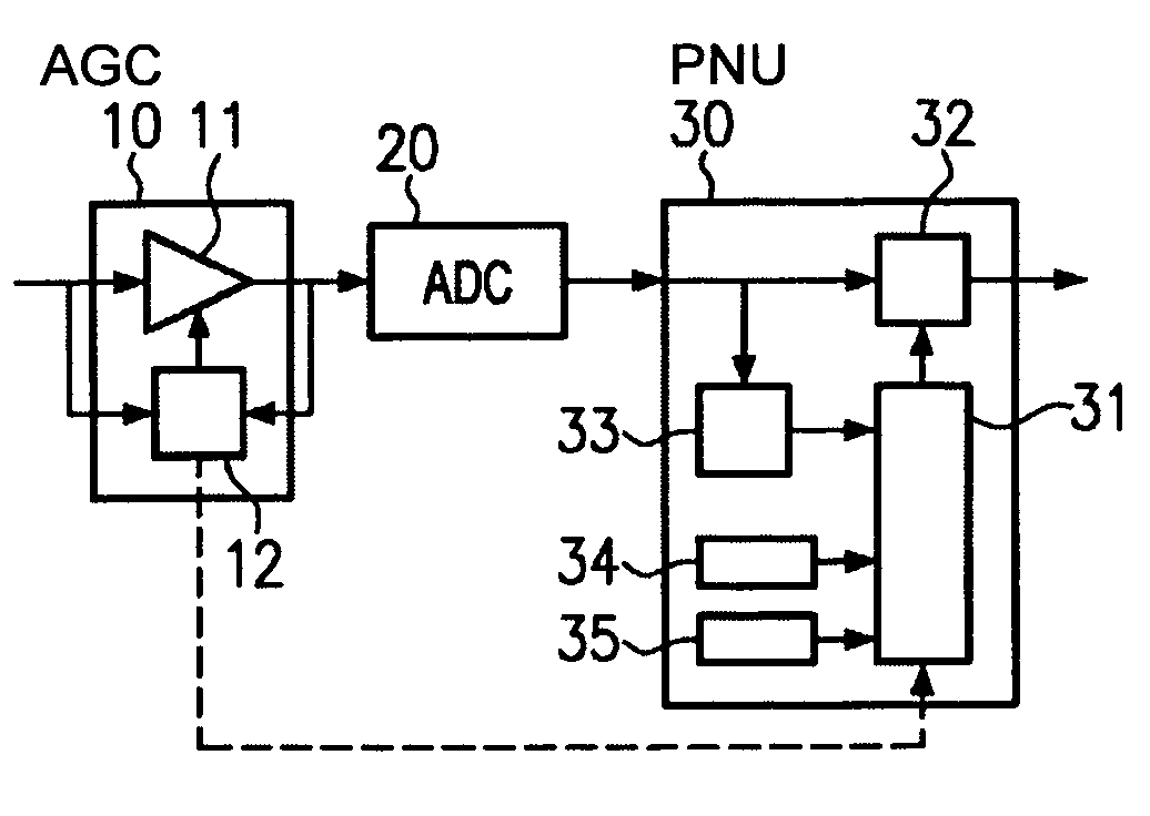
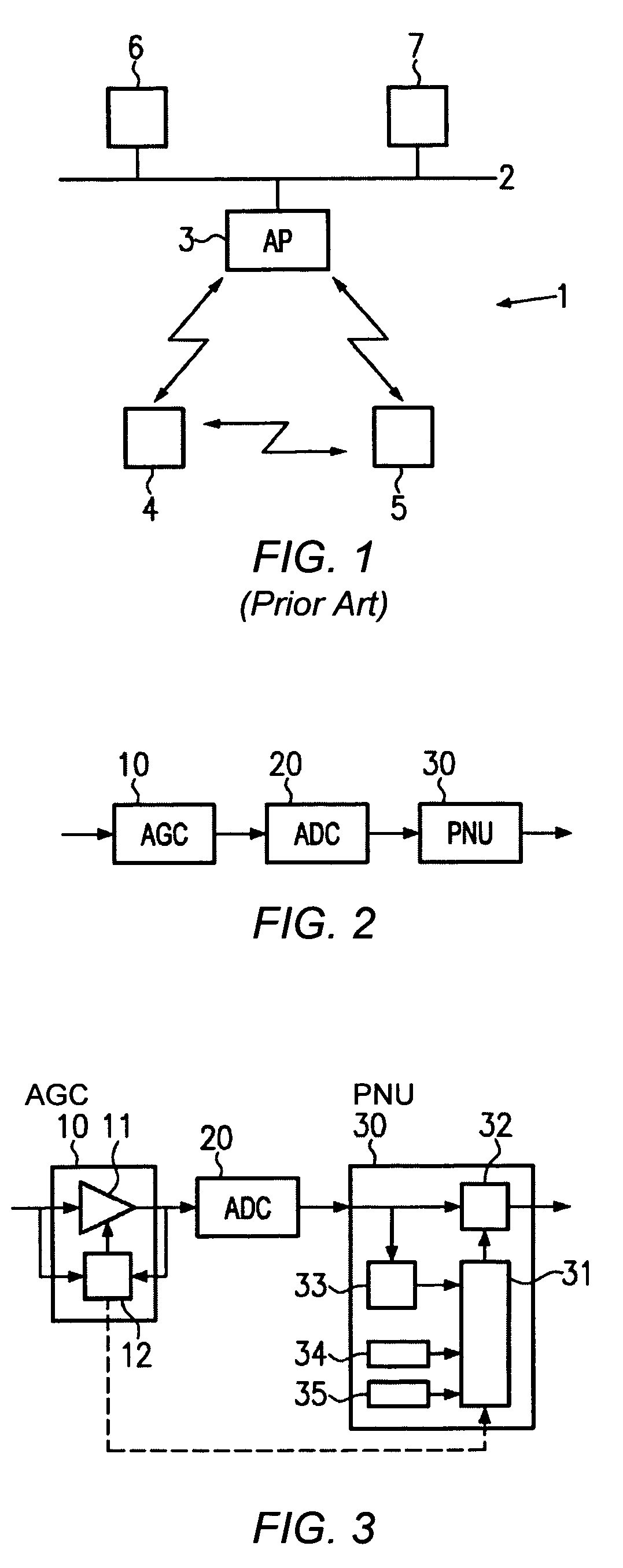
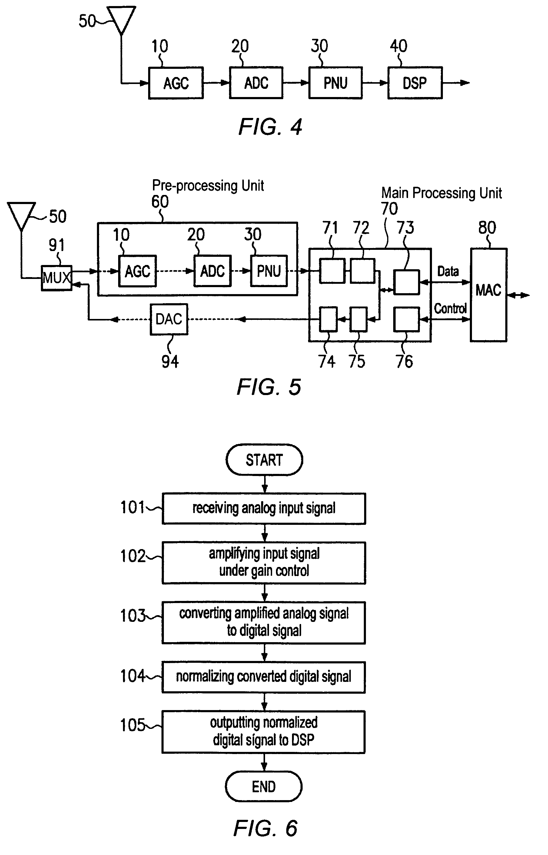
[0023]FIG. 2 illustrates a pre-processing device for use in a wireless LAN node such as a station or access point. The pre-processing device comprises an AGC unit 10, an ADC unit 20 and a power normalization unit 30. The AGC unit 10 receives an analog input signal for amplifying same under gain control. Accordingly it outputs an amplified analog signal. The ADC unit 20 is connected to the AGC unit 10 for receiving the amplified analog signal. The ADC unit 20 converts the received analog signal into a digital signal and outputs same. The power normalization unit 30 is connected to the ADC unit 20, receives the digital signal and applies a power normalization function to the received digital signal. Then it provides or outputs a normalized digital signal.

[0024]In the pre-processing device illust...


PUM


Abstract

A signal pre-processing device particularly in wireless LAN devices is provided that comprises an AGC (Automatic Gain Control) unit, an ADC (Analog-to-Digital Converting) unit and a normalization unit. The AGC unit amplifies a received analog input signal and outputs an amplified analog signal. Further, it automatically controls an amplification gain when amplifying the analog input signal. The ADC unit receives the amplified analog signal, converts it into a digital signal and outputs the digital signal. The normalization unit is receives the digital signal, applies a normalization function to the digital signal and outputs the normalized digital signal. Thus, less precise AGC units can be used, thereby reducing production costs as well as the size and complexity of the AGC unit. Further, shorter circuit development times are obtainable.

Description

BACKGROUND OF THE INVENTION[0001]1. Field of the Invention[0002]The invention generally relates to wireless LAN (Local Area Network, WLAN) systems and in particular to gain controlled wireless LAN devices such as receivers, access points or stations, and corresponding methods that provide or use a digital signal having a normalized signal level.[0003]2. Description of the Related Art[0004]A wireless LAN system is a flexible data communication system that allows a remote user's mobile device to connect to an access point of the network (wired LAN), without having the requirement for the mobile device of being physically attached to the network, as well as to connect to a further remote user device. Thus the mobile device in a wireless LAN system provides for wireless mobility and additionally achieves the common functionality of wired data transfer as well as application and data access via the network.[0005]As illustrated in FIG. 1, a wireless LAN 1 provides connection for mobile de...

Claims


Application Information

Patent Timeline
IPC IPC(8): H04L27/08H03G3/00H03G3/30
CPCH03G3/3089H03G3/001
Inventor KLUGE, WOLFRAMBOROWSKI, JORGPOEGEL, FRANK
Owner GLOBALFOUNDRIES US INC
Learn More