Eureka AIR delivers breakthrough ideas for toughest innovation challenges, trusted by R&D personnel around the world.

Communication control apparatus and method

a communication control and apparatus technology, applied in the field of communication control apparatus and methods, can solve the problems of not being able to check the current functional settings of all the nodes on the communication network, not being able to readily know or ascertain which nodes (networked devices) are connected with which nodes (networked devices) for data communication, and requiring laborious and time-consuming operations, so as to facilitate identification of actual connecting states

Active Publication Date: 2007-01-02
YAMAHA CORP
View PDF18 Cites 129 Cited by
  • Summary
  • Abstract
  • Description
  • Claims
  • Application Information

AI Technical Summary

Benefits of technology

[0006]It is therefore an object of the present invention to provide a communication control apparatus and method which can facilitate identification of actual connecting states between a plurality of networked nodes.
[0007]It is another object of the present invention to provide a communication control apparatus and method which allow actual connecting states between a plurality of networked nodes to be readily set and changed.
[0008]It is still another object of the present invention to provide a communication control apparatus and method which can facilitate an operation for changing a node to which a particular function, such as a word clock master node.
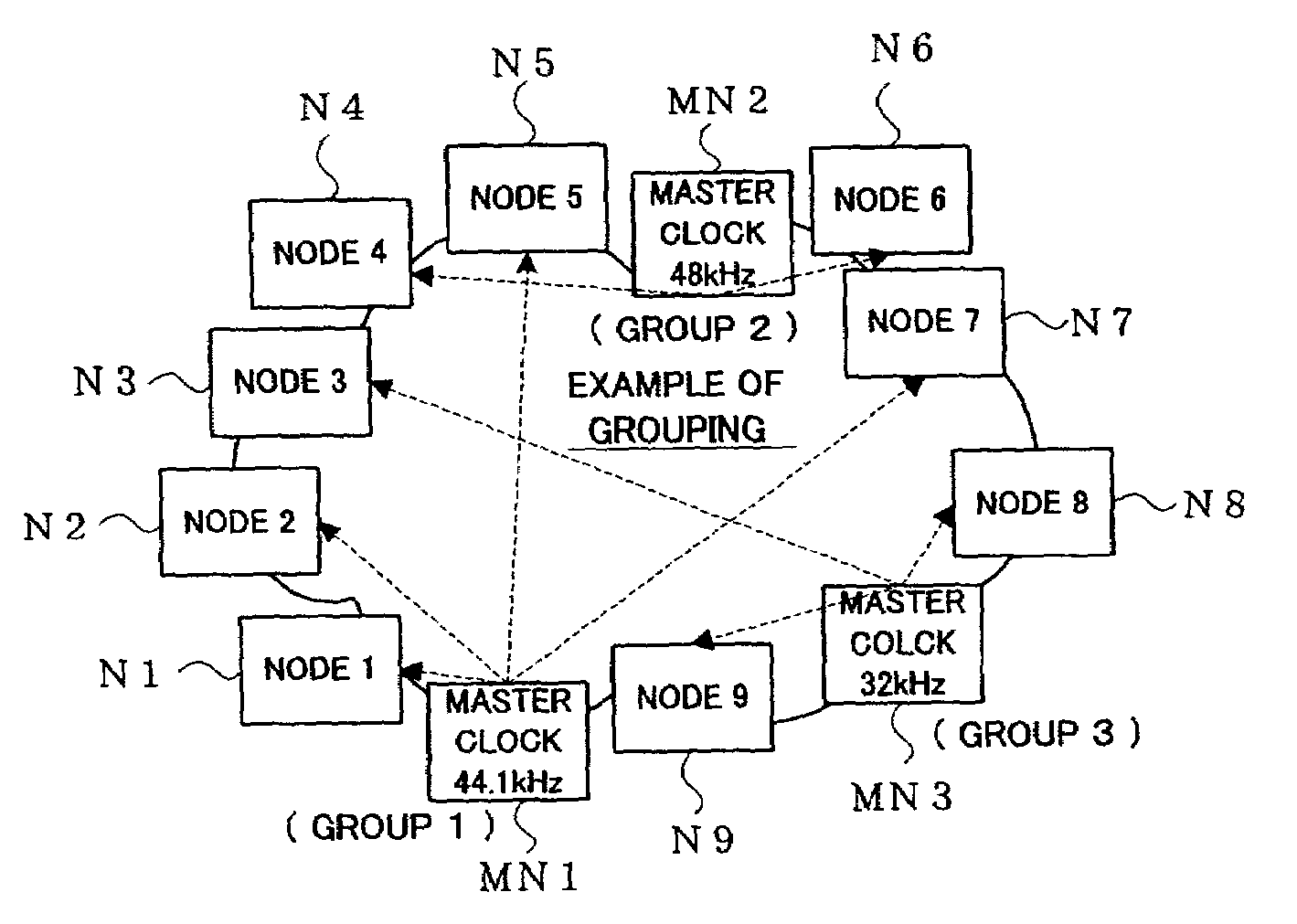
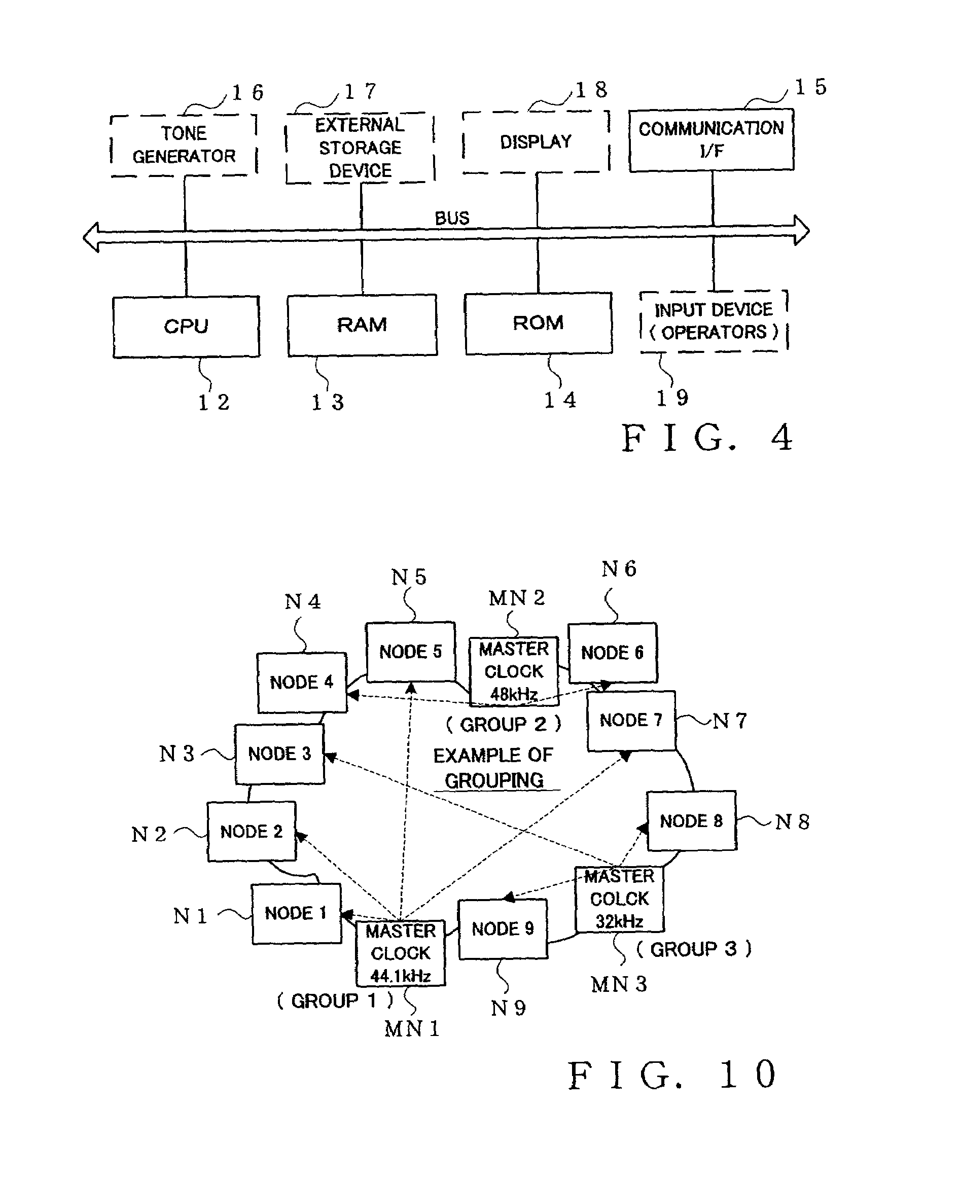
[0010]With such arrangements, just checking the group identification information of each of the nodes can ascertain which nodes are actually connected with which nodes (actual data communicating relationships between the nodes) and hence can identify actual states of connection among the nodes. Further, by just changing a node group, to which a given node belongs, to another node group, it is possible to establish connection with all nodes present in the other node group. As a result, the present invention can readily set actual connecting states between a plurality of nodes and change contents of the thus-set connecting states as necessary.
[0012]By performing control such that only one node of a particular function, such as a word clock master node, exists in one node group, the present invention can readily change settings about the nodes, such as one for changing the node of the particular function from one node over to another. For example, the node of the particular function can be appropriately changed from one node over to another, without having to rearrange the classification of the nodes into node groups. Thus, with the present invention, the setting about the node of the particular function, such as a word clock master node, can be changed with ease.

Problems solved by technology

However, in the case where the IEEE 1394 standard or USB standard is employed, tone-related signals, control signals and various other signals pertaining to the networked devices are transferred over the single signal path and the individual nodes (individual networked devices) are connected with one another via the single signal path, so that it is almost impossible to readily know or ascertain which nodes (networked devices) are connected with which nodes (networked devices) for data communication (actual data transmitting / receiving relationships among the nodes) or what kind of data are being transmitted / received or communicated among the nodes.
But, because the daisy chain with the nodes linked together via the single signal path may be expanded infinitely, it is not at all advisable to check the current functional settings in all the nodes on the communication network.
Further, in a situation where a real-time ensemble performance is to be executed by a plurality of nodes, to change the word clock master node (that provides a synchronization basis for communication of tone-related signals between the nodes via the communication network) from one master node having a given clock frequency over to another master node having another clock frequency, the settings about the word clock master node must be changed in each of the slave nodes, which would require very laborious and time-consuming operations.

Method used


Image

  • Communication control apparatus and method
  • Communication control apparatus and method
  • Communication control apparatus and method

Examples


Embodiment Construction

[0026]Before going into detailed description of the invention based on the drawings, some key features of the embodiments to be later detailed will first be explained briefly.

[0027]Communication control apparatus in accordance with en embodiment of the present invention comprises: a group setting section that selects one or more nodes from among a plurality of nodes connected to a communication network and classifies the selected nodes as one node group; and a registration section that, in association with each of the nodes classified as the one node, registers group identification information for identifying the node group. In this apparatus, nodes constituting a same node group that should at least commonly receive data can be identified by the group identification information.

[0028]As one example, the group setting section may be arranged to select a plurality of nodes and establishes a new node group composed of the selected nodes. As another example, the group setting section m...


PUM


Abstract

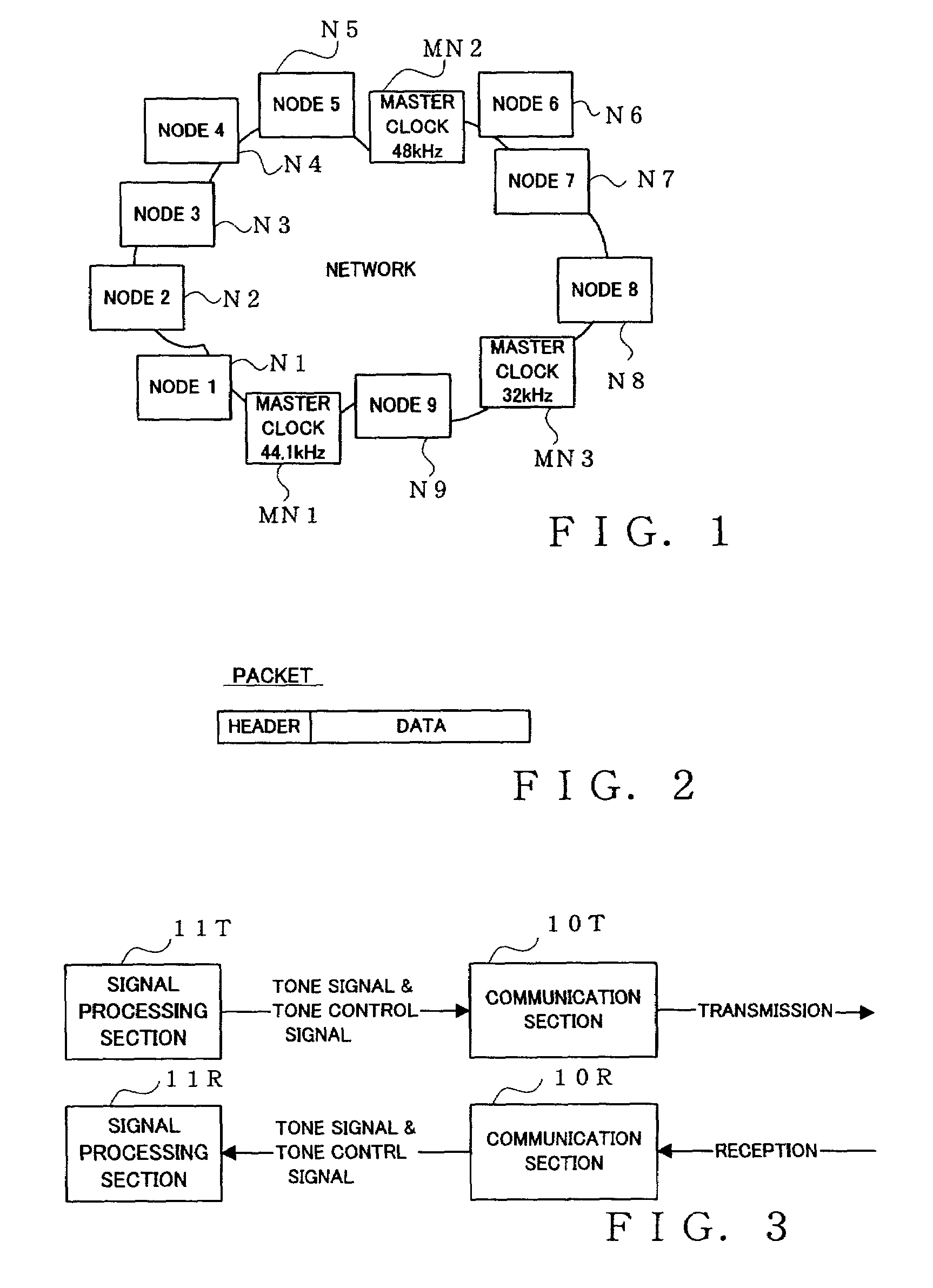
One or more nodes on a communication network are selected and set as one node group. In each of the nodes, group identification information representing the node group to which the node belongs is stored in advance. The group identification information is attached to the header of a data packet to be transmitted, so that nodes constituting a node group that should commonly receive data can be readily identified by comparing the group identification information imparted to the transmitted data packet and the group identification information stored in each receiving node. Given node can choose to become a node of a particular function, such as a clock master node, in which case control is performed to delete, from the node group, a node having so far played the role of the node of the particular function in such a manner that there exists only one node of the particular function per node group.

Description

BACKGROUND OF THE INVENTION[0001]The present invention relates generally to a technique for communicating data containing tone-related signals, such as music performance data like audio data or MIDI data, between a plurality of nodes via a communication network, and more particularly to an improved communication control apparatus and method for use in such data communication.[0002]In recent years, audio / video systems are built by interconnecting many electronic devices, such as a video display device, video tape recorder, audio components and karaoke device. In the field of electronic musical instruments, an ensemble performance system or the like are built by interconnecting a plurality of electronic musical instruments or interconnecting a sequencer, personal computer and the like using a unified standard, such as the well-known MIDI (Musical Instrument Digital Interface) standard. Techniques for communicating tone-related signals between a plurality of nodes interconnected via a ...

Claims


Application Information

Patent Timeline
Patent Type & Authority Patents(United States)
IPC IPC(8): H04J3/24H04B7/212H04J3/06H04L12/28G06F13/00G10H1/00H01S5/227H01S5/34H04L7/00H04L29/02
CPCB82Y20/00G10H1/0058H01S5/227H04L7/0079H04J3/0641G10H2240/175H04H60/04H04J3/0661H04L7/0029
Inventor FUJIMORI, JUNICHI
Owner YAMAHA CORP
Why Eureka
Eureka Blog
Learn More