System and method for attenuating the effect of ambient light on an optical sensor

a technology of ambient light and optical sensor, which is applied in the field of optical sensors, can solve problems such as negative affecting the accuracy of optical sensors

Inactive Publication Date: 2007-01-02
SENSEONICS INC
View PDF8 Cites 163 Cited by
  • Summary
  • Abstract
  • Description
  • Claims
  • Application Information

AI Technical Summary

Benefits of technology

[0009]In another aspect, the present invention provides methods for using and implanting an optical sensor, which methods, used together or separately, reduce the effect of ambient light on the optical sensor.

Problems solved by technology

In some circumstances, a significant amount of ambient light may negatively affect the accuracy of an optical sensor.

Method used


Image

  • System and method for attenuating the effect of ambient light on an optical sensor
  • System and method for attenuating the effect of ambient light on an optical sensor
  • System and method for attenuating the effect of ambient light on an optical sensor

Examples


Embodiment Construction

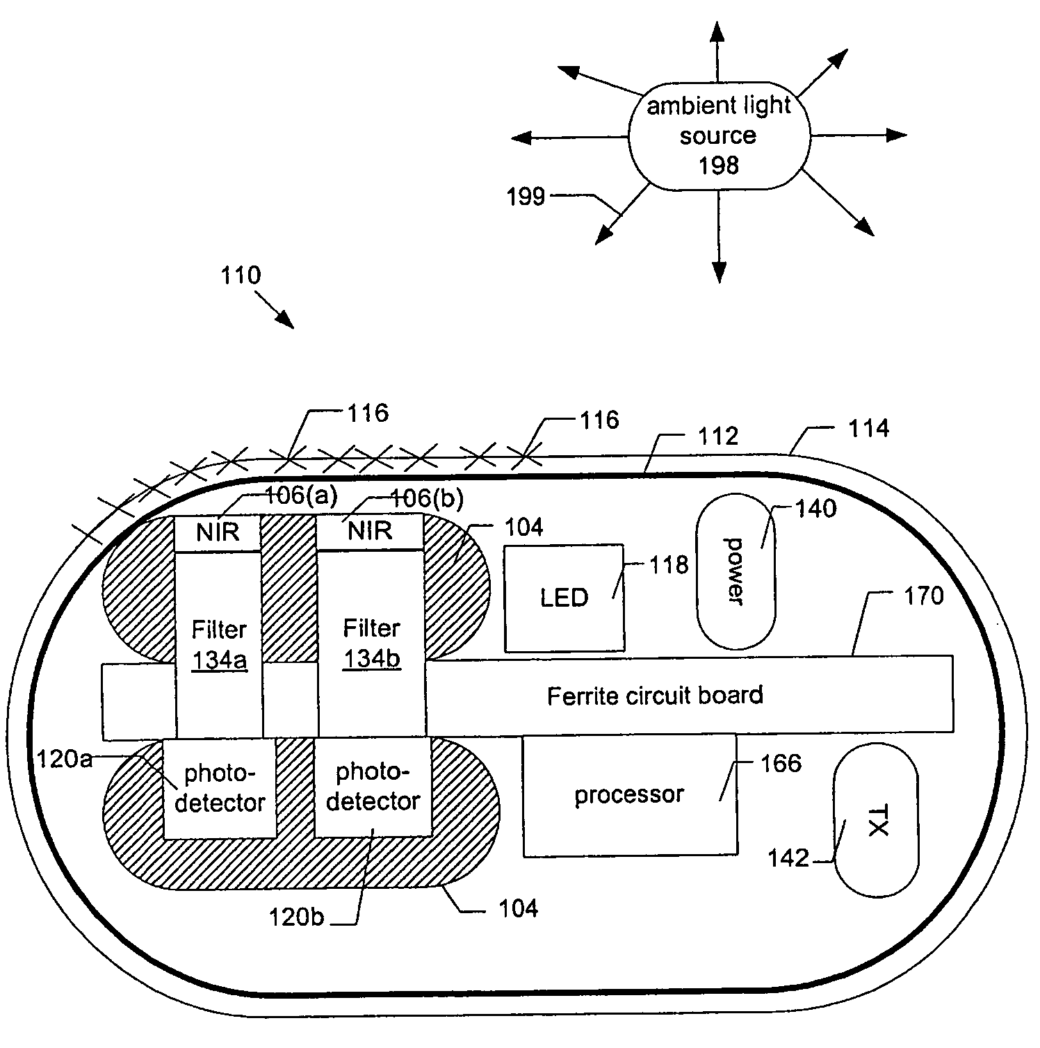
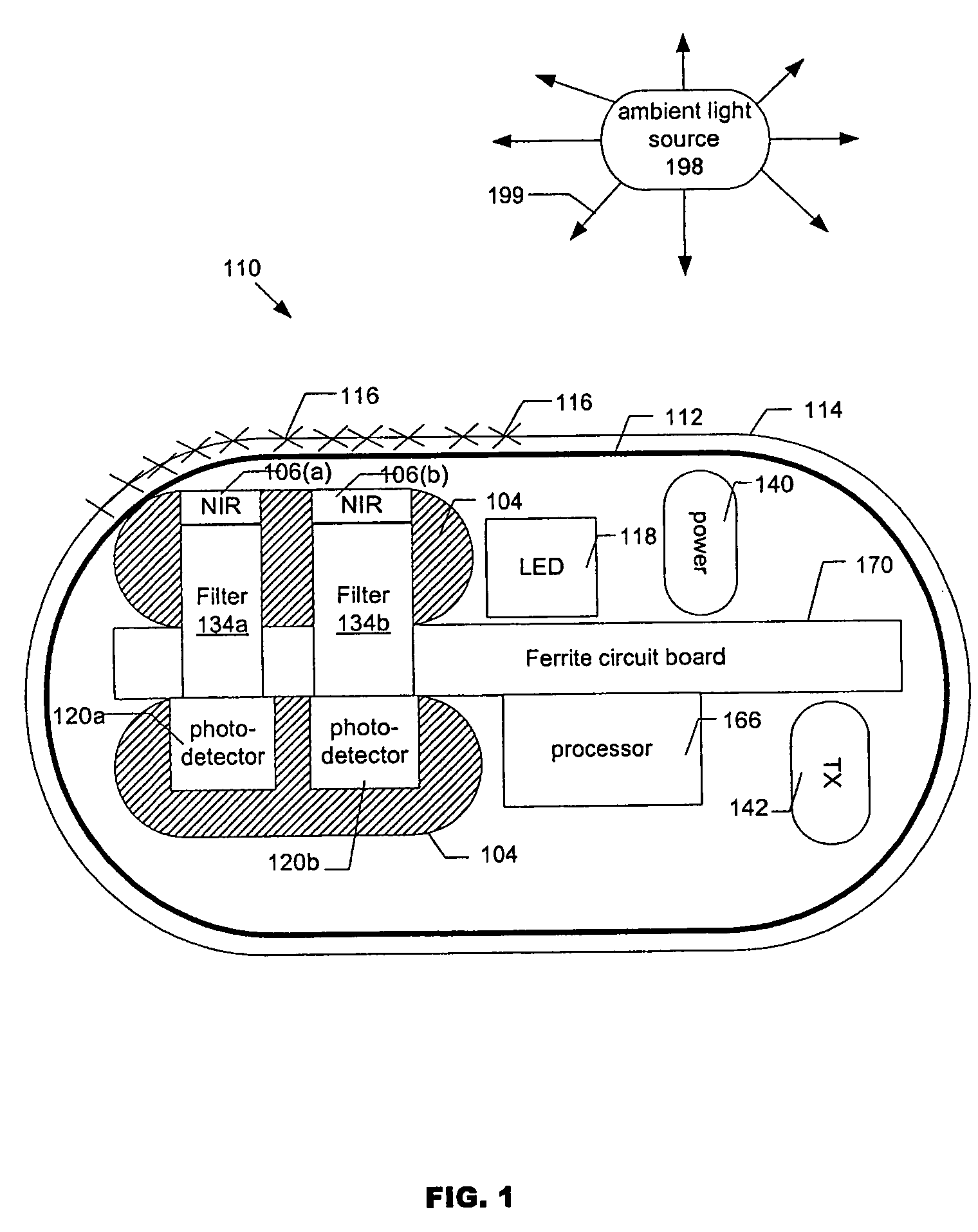
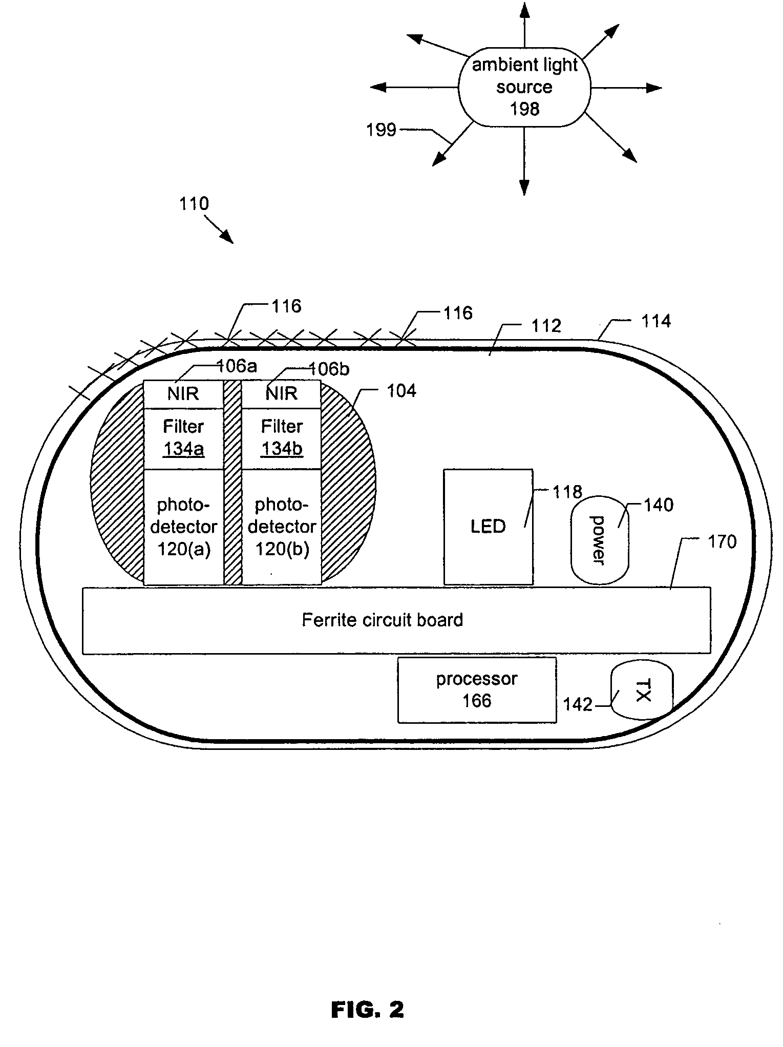
[0024]FIG. 1 shows an optical sensor (“sensor”) 110, according to an embodiment of the present invention, that operates based on the fluorescence of fluorescent indicator molecules 116. The sensor 110 includes a sensor housing 112 (sensor housing 112 may be formed from a suitable, optically transmissive polymer material), a matrix layer 114 coated over the exterior surface of the sensor housing 112, with fluorescent indicator molecules 116 distributed throughout the layer 114 (layer 114 can cover all or part of the surface of housing 112); a radiation source 118, e.g. an LED, that emits radiation, including radiation over a range of wavelengths which interact with the indicator molecules 116, i.e., in the case of a fluorescence-based sensor, a wavelength which causes the indicator molecules 116 to fluoresce; and a photodetector 120 (e.g. a photodiode, phototransistor, photoresistor or other photodetector) which, in the case of a fluorescence-based sensor, is sensitive to fluorescent...


PUM

PropertyMeasurementUnit
fluorescentaaaaaaaaaa
fluorescenceaaaaaaaaaa

Abstract

The present invention provides systems and methods for attenuating the effect of ambient light on optical sensors and for measuring and compensating quantitatively for the ambient light.

Description

[0001]The present application claims the benefit of U.S. Provisional Patent Application No. 60 / 462,695, filed Apr. 15, 2003.BACKGROUND OF THE INVENTION[0002]1. Field of the Invention[0003]The present invention relates to optical sensors, and, more specifically, to a system and method for attenuating the effect of ambient light on an optical sensor.[0004]2. Discussion of the Background[0005]An optical sensor is a device that may be used to detect the concentration of an analyte (e.g., oxygen, glucose, or other analyte). U.S. Pat. No. 6,330,464, the disclosure of which is incorporated herein by reference, describes an optical sensor.[0006]There may be situations when it is desirable to use an optical sensor in an environment where there is a significant amount of ambient light (e.g., the outdoors on a bright, sunny day). In some circumstances, a significant amount of ambient light may negatively affect the accuracy of an optical sensor. Accordingly, what is desired are systems and met...

Claims


Application Information

Patent Timeline
Patent Type & Authority Patents(United States)
IPC IPC(8): F21V9/16A61B5/00G01N21/64H05K1/02H05K1/03H05K1/16H05K3/40
CPCA61B5/0031A61B5/14532A61B5/14556A61B5/1459A61B5/681G01N21/6428H05K1/165G01N21/645H05K2201/10106G01N2201/1244H05K1/0306H05K3/403H05K2201/086H05K2201/09972G01N21/64A61B5/00
Inventor COLVIN, ARTHUR EARLZERWEKH, PAUL SAMUELLESHO, JEFFREY C.LYNN, ROBERT WILLIAMLORENZ, CARRIE R.O'CONNOR, CASEY J.WALTERS, STEVEN J.
Owner SENSEONICS INC
Why Eureka
Try Eureka