
Handheld infrared camera

a technology of infrared camera and hand held, which is applied in the field of hand-held infrared camera, can solve the problems of not being able to find the actual hot spot efficiently, running the risk of missing the desired target or critical hot spot, and cumbersome and time-consuming procedures, and achieves the effect of convenient operation and good portability

Inactive Publication Date: 2007-01-02
FLIR SYST AB
View PDF32 Cites 56 Cited by
  • Summary
  • Abstract
  • Description
  • Claims
  • Application Information

AI Technical Summary

Benefits of technology

[0005]It is an object of the invention to provide an infrared camera that has good portability and that is easy to operate, preferably with the use of a single hand.
[0006]A further object of the invention is to provide an infrared camera that can stand fairly rough treatment, for use in different and sometimes difficult environments.
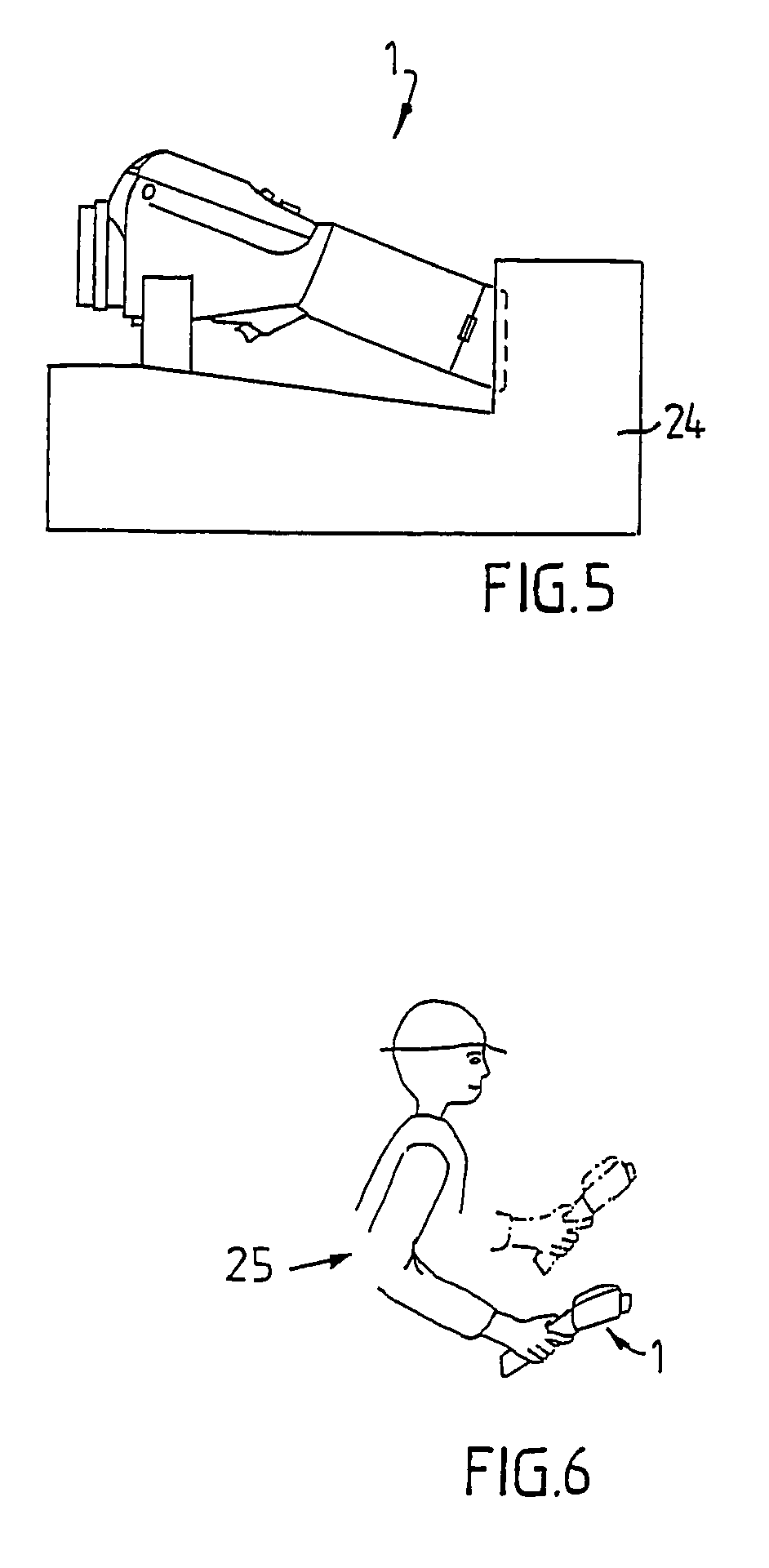
[0009]According to the invention an infrared camera is obtained where the housing is essentially elongate and has the lens assembly mounted at one end while the opposite end is formed as a user handle. On the housing there are provided manual control means for thumb operation by the user, and also a visual control means to be viewed at a distance. This allows easy holding and operating of the camera by one hand, away from the eyes and the body of the user. The inventive camera could advantageously be used for thermographic inspections in various kinds of environments.
[0010]The elongate shape of the housing of the camera, providing a good grip and having no protruding, fragile parts, provides good portability and also helps to provide a rugged design.
[0011]Also, the easy to operate design helps to provide good results from the use of the camera, since a serviceman using it can concentrate more on the actual problem to be solved, rather than to have to struggle with the operation of the camera.

Problems solved by technology

When using a spot pyrometer, however, the operator is running the risk of missing the desired target or the critical hot spot since he has no other way to perform the control than by manually scanning the object by pointing his spot pyrometer in different directions in an effort to find the actual hot spot.
This is sometimes a cumbersome and time-consuming procedure and is not an efficient way to find the actual hot spot.
There is thus a risk that the use of a spot pyrometer might not produce a safe result.
A problem is, however, that normal IR-cameras are rather heavy optical instruments that require careful and gentle handling by two hands.
Such equipment is rather fragile and is not well suited for use in harsh environments where service technicians often have to perform their duties.

Method used


Image

  • Handheld infrared camera
  • Handheld infrared camera
  • Handheld infrared camera

Examples


Embodiment Construction

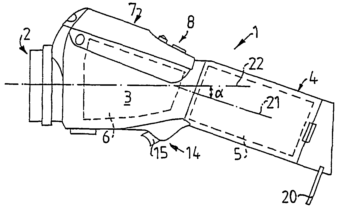
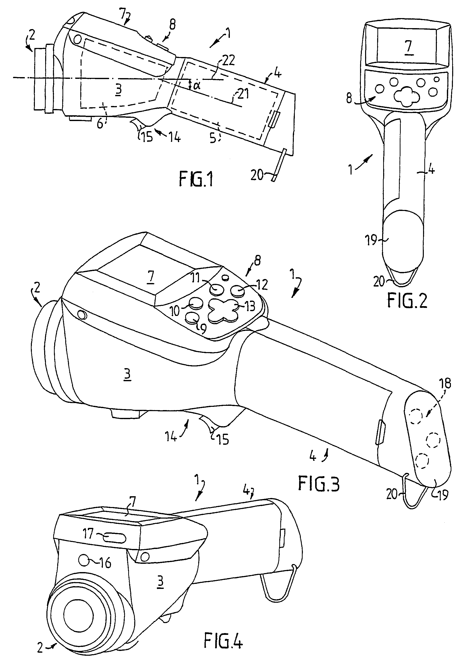
[0019]In FIGS. 1–4 there is shown an infrared camera 1 according to the invention. There is provided a lens assembly 2, which could be exchangeable and which is secured to one end of an essentially elongate housing 3, the opposite end portion 4 of which is formed as a user handle. Inside the housing 3, in the handle portion 4, there is provided an electrical energy source 5, suitably in the form of a rechargable battery, but also other options would obviuosly be possible. Inside the housing 3 there is also provided a handling unit 6 for receiving and handling information received via the lens assembly 2.

[0020]On the forward portion of the housing 3, ahead of the handle portion 4, there is provided a user interface arrangement for operating the camera 1. Said interface arrangement is intended to provide easy and quick control and operation of the camera visually and by only one hand. There is thus provided a display 7, which is located up front on the top side of the forward portion ...


PUM


Abstract

A handheld infrared camera having a lens assembly, an electric energy source and a handling elements for recording and handling information received via the lens assembly has an essentially elongate housing. The lens assembly is mounted at one end of the housing, the other end portion of which is formed as a user handle, the longitudinal axis of which preferably is inclined relative to the optical axis of the lens assembly to form an angle (αalpha) with the optical axis. There are provided manual control elements for allowing single hand operation of the camera, and a visual control elements is intended to be viewed when holding and operating the camera away from the eye and the body of a user. The camera is advantageously provided with elements for wireless transmission of information from the camera.

Description

TECHNICAL FIELD[0001]The present invention relates to a handheld infrared camera.BACKGROUND OF THE INVENTION[0002]It is becoming more and more common to use various kinds of special non-contact equipment for controlling the local temperature of various items in order to find out the status of the item. It is for instance well known to look for heat leaks by means of non-contact infrared equipment in order to be able to perform the control at a certain distance from the object. Also, spot pyrometers (non-contact thermometers) are used in a number of applications like food safety, car manufacturing and repair, inspection of aircraft, etc. When using a spot pyrometer, however, the operator is running the risk of missing the desired target or the critical hot spot since he has no other way to perform the control than by manually scanning the object by pointing his spot pyrometer in different directions in an effort to find the actual hot spot. This is sometimes a cumbersome and time-con...

Claims


Application Information

Patent Timeline
IPC IPC(8): G01J5/02G01J1/06G01J5/10G01J5/48G03B42/00H04N5/225H04N5/33
CPCG01J5/025G01J5/0265G01J2005/0077
Inventor HAMRELIUS, TORBJORNLANNESTEDT, TOMAS
Owner FLIR SYST AB
Learn More