Method of forming a perimeter weighted foundation for wind turbines and the like

Inactive Publication Date: 2007-01-02
TERRACON CONSULTANTS INC
View PDF20 Cites 61 Cited by
  • Summary
  • Abstract
  • Description
  • Claims
  • Application Information

AI Technical Summary

Benefits of technology

[0022]The perimeter weighted foundation of the present invention incorporates the above described post-stressed annular foundation of my prior patents as a pier pedestal or pedestal section of the foundation of the present invention. The present invention differs from the structures disclosed in my prior patents in that the foundation of the present invention includes an expanded base positioned adjacent the bottom of the pedestal section which has a cylindrical perimeter wall that is substantially larger in diameter than the cylindrical wall of the pedestal section and that extends to a depth substantially below the bottom of the pedestal section. The expanded base also includes a generally horizontal disk-like spread section which interconnects the bottom of the pedestal section and the top of the perimeter wall or perimeter wall section. This combination greatly increases the foundation's resistance to an overturning moment by use of skin friction along the exterior sides of the perimeter wall and pedestal section and by the additional weight and size concentration at the perimeter of the foundation, including the back fill on top of the horizontal spread section.
[0023]The foundation of the present invention also eliminates alternating cyclical compression and tension loading stresses, thereby substantially increasing internal stiffness and reducing fatigue. Vertically extending anchor bolts in the pedestal section are sleeved in PVC or equivalent shielding to prevent bolt bonding with concrete for compression of the concrete as disclosed in my prior patents. Radially extending bolts are embedded horizontally in the disk-like spread section for reinforcement. The radially extending horizontal bolts are also sleeved in PVC or equivalent sheathing for high compression loading of the annular spread section. It has not been found necessary to post-tension the cylindrical perimeter wall and post-tension bolts are preferably omitted from this section. However, such bolts may be included as part of the present invention if high unit compression of the exterior perimeter wall section is desired.
[0024]The foundation of the present invention reduces time, and reduces cost by allowing excavation by conventional backhoes and / or track excavators. Further, the tensionless pedestal section can be assembled and poured at a fabrication yard and shipped as a precast component to the foundation site. The corrugated metal pipe (CMP) forms provide reinforcing steel and establish a boundary for the concrete pour. The bolt holes in the CMP provide support and positioning for the horizontal radial arrangement of the laterally extending bolts in the spread section, along with eliminating the need for temporary perimeter forms and reinforcing steel supporting chairs and blocks. The foundation may be poured continuously (monolithically) or sequentially, first the perimeter wall, then the spread section and finally the pedestal section. Alternatively, the pedestal section can be poured first, then the perimeter wall and finally the spread section in two separate pours.

Problems solved by technology

The large foundation typically requires a great amount of reinforcing steel and a large amount of concrete to encase the reinforcing steel.

Method used


Image

  • Method of forming a perimeter weighted foundation for wind turbines and the like
  • Method of forming a perimeter weighted foundation for wind turbines and the like
  • Method of forming a perimeter weighted foundation for wind turbines and the like

Examples


Embodiment Construction

[0057]Although only two preferred embodiments of the invention are explained in detail, it is to be understood that the embodiments are given by way of illustration only. It is not intended that the invention be limited in its scope to the details of construction and arrangement of components set forth in the following description or illustrated in the drawings. Also, in describing the preferred embodiments, specific terminology will be resorted to for the sake of clarity. It is to be understood that each specific term includes all technical equivalents which operate in a similar manner to accomplish a similar purpose.

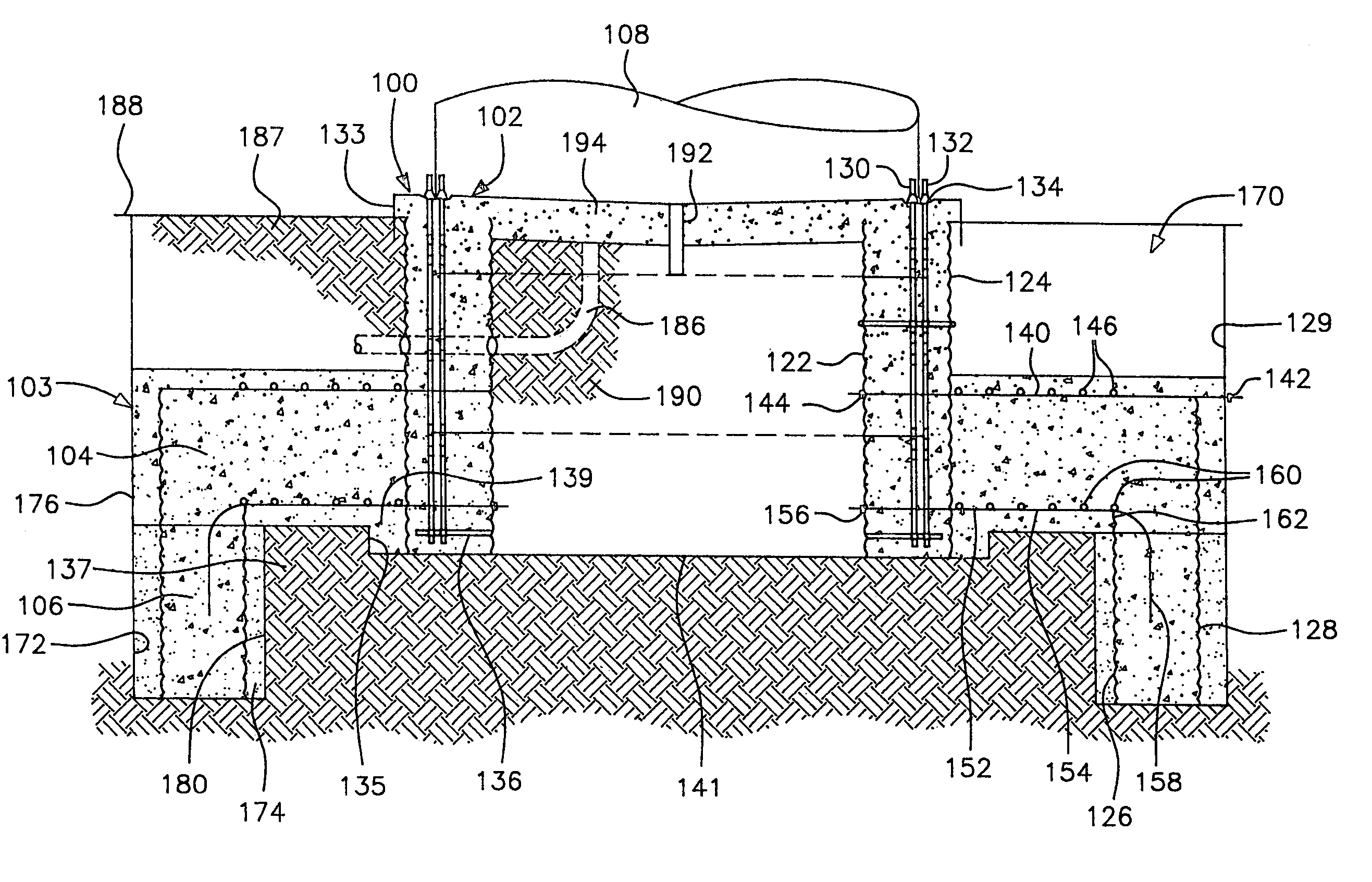
[0058]Referring now more specifically to the drawings directed to the present invention, especially FIGS. 3, 4 and 5, the reference numeral 100 generally designates the perimeter weighted foundation of the instant invention. The foundation 100 includes a pier pedestal or pedestal section 102 and an expanded base, generally designated by reference numeral 103. The expan...


PUM


Abstract

A perimeter weighted foundation has a central pier pedestal and an enlarged base spaced outwardly and extending below the pedestal. The enlarged base includes an outer concentric perimeter wall section with a radially extending, disk-shaped spread section interconnecting the bottom of the pedestal section and the top of the perimeter wall section. The pedestal section includes vertically extending post-tensioning anchor bolts sleeved through substantially the entire height of the cylindrical pedestal in accordance with earlier U.S. Pat. Nos. 5,586,417 and 5,826,387 and the spread section includes two layers of similarly sleeved post-tensioning bolts which extend through the bottom of the pedestal section and into or through the top of the perimeter wall section, thus tying together the enlarged base to the pier pedestal. After the concrete is poured, hardened and cured, the vertical bolts of the pedestal section and the radially extending horizontal bolts in the spread section are post-tensioned to impart a heavy unit compressive loading on the concrete in the pier pedestal and enlarged base. After back filling soil onto the spread section and to the interior of the pedestal section, the foundation is able to withstand high upset forces imparted to the foundation by any large structure supported thereon.

Description

[0001]This is a division of application Ser. No. 10 / 067,999, filed Feb. 8, 2002, now U.S. Pat. No. 6,672,023 issued Jan. 6, 2004, which in turn is a continuation of application Ser. No. 09 / 671,282 filed Sep. 27, 2000, now abandoned, the disclosure thereof being incorporated by reference as if fully set forth herein.BACKGROUND OF THE INVENTION[0002]1. Field of the Invention[0003]This invention relates to concrete foundations, and more particularly, to reinforced concrete pier foundations useful for the support of tall, heavy and / or large towers which may be used to support power lines, communication systems, street lighting and signals, bridge supports, commercial signs, freeway signs, ski lifts and the like, and especially wind turbines which are subject to very high upset forces.[0004]2. Background of the Invention[0005]Various different forms of foundations utilizing some of the general structural and operational features of the instant invention have been known. However, these pr...

Claims


Application Information

Patent Timeline
IPC IPC(8): E04B1/00E04G21/00E04G23/00E02D27/42F03D1/00F03D11/04
CPCE02D27/42E04H12/085F03D11/045Y02E10/728F05B2240/912F03D13/22E02D27/425Y02E10/72
Inventor HENDERSON, ALLAN P.
Owner TERRACON CONSULTANTS INC
Why Eureka
Try Eureka