
Very-high aperture projection objective

a projection objective and very high aperture technology, applied in the field of projection objectives, can solve the problems of increasing the cost of such projection objectives, difficult to provide very high aperture systems with adequate small chromatic aberrations, and increasing the volume of optical lens materials, so as to improve chromatic correction, save material, and high image-side numerical aperture

Inactive Publication Date: 2006-12-26
CARL ZEISS SMT GMBH
View PDF15 Cites 85 Cited by
  • Summary
  • Abstract
  • Description
  • Claims
  • Application Information

AI Technical Summary

Benefits of technology

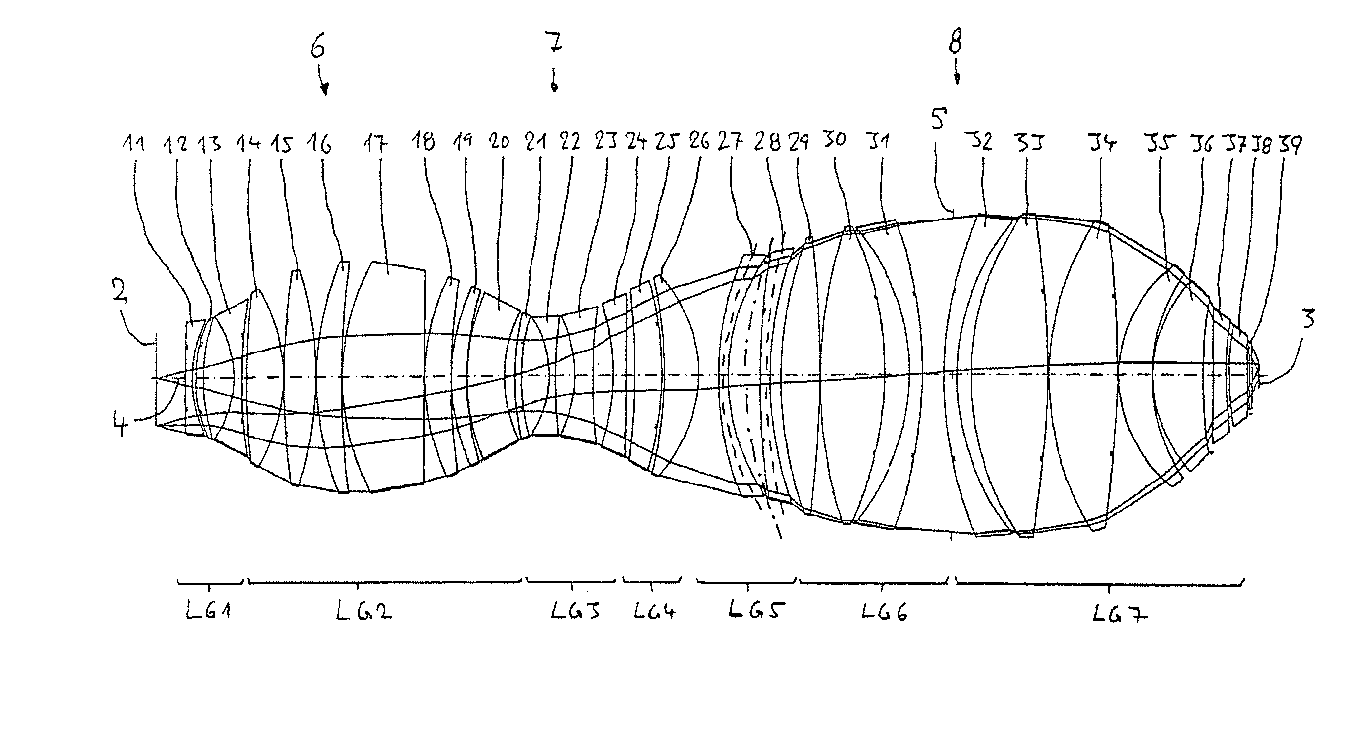
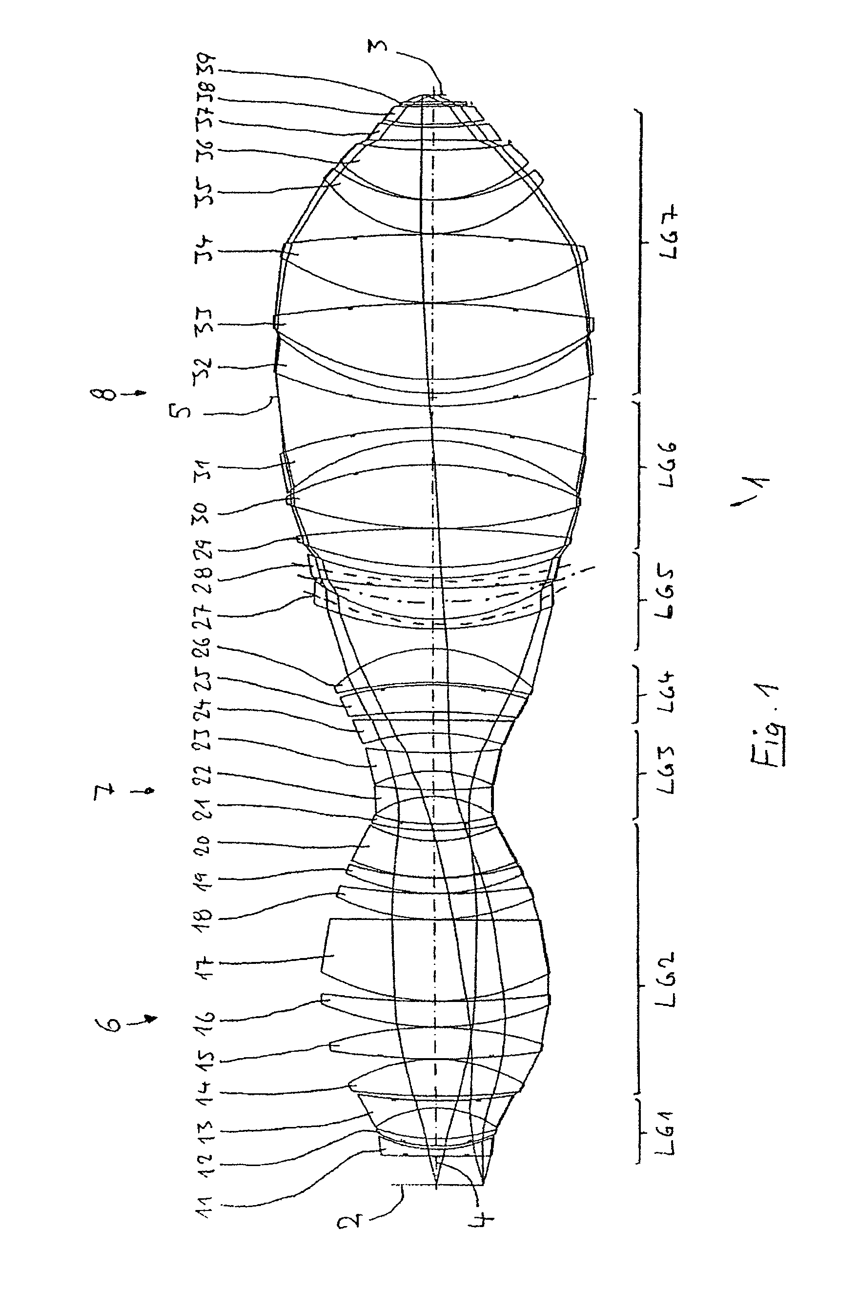
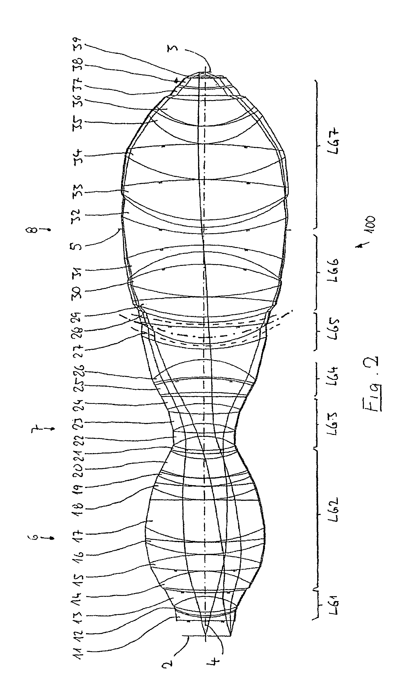
The invention provides a projection objective with a high image-side numerical aperture and improved chromatic correction. The objective has a multiplicity of optical elements arranged along an optical axis and a system diaphragm at a distance in front of the image plane. The objective is designed as a purely refractive single-waist system with a belly near the object and a belly near the image. The negative group, which acts on high incidence angles, is bent as a whole relative to the beam path and has an effective curvature with a concave side directed towards the image. The negative group can be a single lens or multiple lenses with negative refractive power. The invention allows for a compact design with a reduced material usage and lower costs.

Problems solved by technology

This raises problems for a partial achromatization, and even more so with a complete achromatization of the projection objectives, that is to say the far-reaching avoidance or reduction of chromatic aberrations.
In particular, it is difficult to provide very high aperture systems with adequate small chromatic aberrations.
In particular, the increase in volume of the optical lens material increases the cost of such projection objectives disproportionately in relation to the gain in reducing structural width.

Method used


Image

  • Very-high aperture projection objective
  • Very-high aperture projection objective
  • Very-high aperture projection objective

Examples


Embodiment Construction

[0047]In the following description of the preferred embodiment, the term “optical axis” denotes a straight line through the centers of curvature of the spherical optical components or through the axes of symmetry of aspheric elements. Directions and distances are described as on the image side, on the wafer side or towards the image when they are directed in the direction of the image plane or the substrate which is located there and is to be exposed, and as on the object side, on the reticle side or towards the object when they are directed towards the object with reference to the optical axis. In the examples, the object is a mask (reticle) with the pattern of an integrated-circuit, but another pattern, for example a grating, can also be involved. In the examples, the image is formed on a wafer serving as substrate and provided with a photoresist layer, but other substrates are also possible, for example elements for liquid crystal displays or substrates for optical gratings.

[0048...


PUM

PropertyMeasurementUnit
operating wavelengthaaaaaaaaaa

Abstract

A very-high aperture, purely refractive projection objective is designed as a two-belly system with an object-side belly, an image-side belly and a waist (7) situated therebetween. The system diaphragm (5) is seated in the image-side belly at a spacing in front of the image plane. Arranged between the waist and the system diaphragm in the region of divergent radiation is a negative group (LG5) which has an effective curvature with a concave side pointing towards the image plane. The system is distinguished by a high numerical aperture, low chromatic aberrations and compact, material-saving design.

Description

[0001]The present application is a Continuation-in-Part of U.S. application Ser. No. 10 / 428,946, filed on May 5, 2003, the disclosure of which is incorporated into this application by reference, and of International Application PCT / US03 / 06592, with an international filing date of Mar. 3, 2003, which was published under PCT Article 21(2) in English, and the disclosure of which is also incorporated into this application by reference; the present application is further based on German Patent Application No. 102 24 361.1 filed on May 24, 2002, on International Patent Application PCT / EP02 / 04846 filed on May 3, 2002, and on U.S. Provisional Application No. 60 / 360,845 filed on Mar. 1, 2002, the three respective disclosures of which are also incorporated into this application by reference.BACKGROUND OF THE INVENTION[0002]1. Field of the Invention[0003]The invention relates to a projection objective for projecting a pattern arranged in the object plane of the projection objective into the im...

Claims


Application Information

Patent Timeline
Patent Type & Authority Patents(United States)
IPC IPC(8): G02B3/00G02B9/00G02B13/14G03F7/20
CPCG02B13/00G02B13/143G03F7/70241G03F7/70958G03F7/70975
Inventor SCHUSTER, KARL-HEINZ
Owner CARL ZEISS SMT GMBH
Learn More