
Method and apparatus for detecting individuals using electrical field sensors

a technology of electrical field and individual detection, applied in the field of individual detection, can solve the problems of requiring a tremendous amount of bandwidth and a human, mechanical sensor type with extremely high false alarm rate, and inability to detect individuals

Inactive Publication Date: 2006-12-26
BAE SYST INFORMATION & ELECTRONICS SYST INTERGRATION INC
View PDF17 Cites 43 Cited by
  • Summary
  • Abstract
  • Description
  • Claims
  • Application Information

AI Technical Summary

Benefits of technology

The system provides a covert, reliable, and energy-efficient means to detect and track individuals without false alarms, using minimal power and remaining undetectable to enemy forces, allowing for precise location and communication of intruder positions.

Problems solved by technology

It has been a common problem, especially in battlefield scenarios, to be able to detect troop movement so that one may know of the presence of hostile forces, whether they are assembled in a group or individually.
However, this type of mechanical sensor has an extremely high false alarm rate, for instance, when tree limbs or the like fall on them, animals trip over them or are activated by high winds, lightning and other anomalies.
Infrared has been used in the past to detect the presence of individuals but the use of infrared as a medium is problematic due to changes in scene illumination, such as changes that can occur when a cloud goes overhead.
Video surveillance is a known technique but requires a tremendous amount of bandwidth and a human being to review the reconstruction of the video scene to ascertain when a person is intruding.
However, pattern recognition requires a large amount of computer overhead, is not necessarily portable and oftentimes fails with changes in the scene, for instance, due to fluttering leaves, moving branches and the like.
However, radar only reflects off of objects having a high radar cross-section and is not often used because the radar systems are active systems that reveal their existence and location.

Method used


Image

  • Method and apparatus for detecting individuals using electrical field sensors
  • Method and apparatus for detecting individuals using electrical field sensors
  • Method and apparatus for detecting individuals using electrical field sensors

Examples


Embodiment Construction

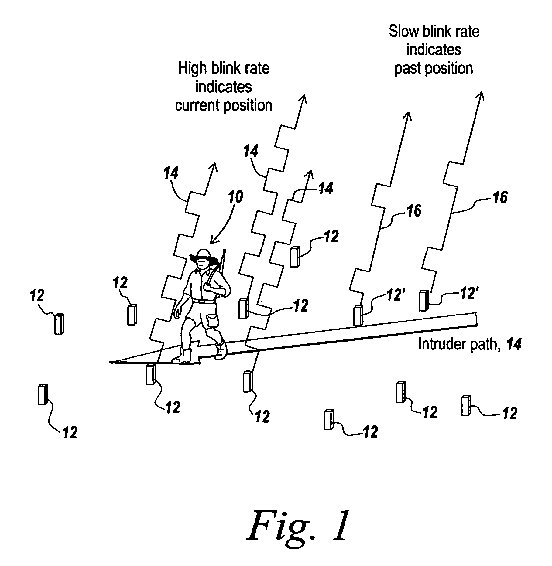
[0070]Referring now to FIG. 1, it is the purpose of the subject invention to be able to detect the presence of a moving individual 10 as he moves past E-field sensors 12 that are scattered about the terrain over which the individual walks or runs.

[0071]The general path of the individual, intruder path 14, is illustrated, which shows that the individual has moved past some of the sensors, is at some of the other sensors and is moving towards further sensors.

[0072]When the sensor detects an E-field tilt corresponding to the presence of an individual within a predetermined perimeter, the sensor emits in one embodiment a pulsed or blinked LED signal 14 to indicate the presence of the individual within a small distance from the sensor. As will be appreciated, these firefly blinking signals can be observed either from above or from ground level and indicate intrusion into the zone protected by the scattered sensors. It is noted that it is not necessary to know the location of the scattere...


PUM


Abstract

A robust, easily deployable, covert, passive intrusion detection system uses one or more E-field sensors to detect the presence of a moving individual and to provide an indication of the presence of the individual adjacent the sensor based on E-field distortion produced by the individual. Single-ended and differential E-field sensors with noise canceling and a guarding circuit provide sufficient sensitivity, with filtering from 0.5 Hz to 8.0 Hz selecting only human intruders. Either visible or invisible flashing light sources at the sensor indicate the presence of a moving individual at the sensor, thus to provide intruder location without the necessity of providing a geolocation system.

Description

CROSS REFERENCE TO RELATED APPLICATIONS[0001]This Application claims rights under 35 USC § 119(e) from U.S. Application Ser. No. 60 / 640,465 filed Dec. 31, 2004. This application is also a continuation-in-part from U.S. application Ser. No. 10 / 917,793 filed Aug. 12, 2004 entitled “Method to Detect and Determine Bearing to a Rocket Launch or Muzzle Blast” by Paul A. Zank et al., which is a continuation-in-part of US Application Serial No. PCT / US03 / 04092 filed Feb. 13, 2003 of the same title; and this application is also a continuation-in-part from U.S. application Ser. No. 10 / 315,561 filed Dec. 10, 2002 by Paul A. Zank et al., entitled “Electric Field Sensor,” now U.S. Pat. No. 6,922,059, the contents all of which are incorporated herein by reference.FIELD OF THE INVENTION[0002]This invention relates to detection of the presence of individuals and more particularly to E-field sensors for detecting the presence of intruders.BACKGROUND OF THE INVENTION[0003]It has been a common problem,...

Claims


Application Information

Patent Timeline
Patent Type & Authority Patents(United States)
IPC IPC(8): G01R29/12G08B13/26
CPCG01V3/088G08B5/38G08B13/26G08B15/001G01R29/12
Inventor ZANK, PAUL A.SUTPHIN, ELDON M.BUCHANAN, DAVID W.SUCCI, GEORGE P.
Owner BAE SYST INFORMATION & ELECTRONICS SYST INTERGRATION INC
Learn More