
Conductive tube for use as a reflectron lens

a technology of dielectric tube and reflector, which is applied in the field of dielectric tube for use as a reflector lens, can solve the problems of complex fabrication and high cost of lens assembly having many discrete components

Active Publication Date: 2006-12-26
PHOTONIS SCI INC
View PDF65 Cites 35 Cited by
  • Summary
  • Abstract
  • Description
  • Claims
  • Application Information

AI Technical Summary

Benefits of technology

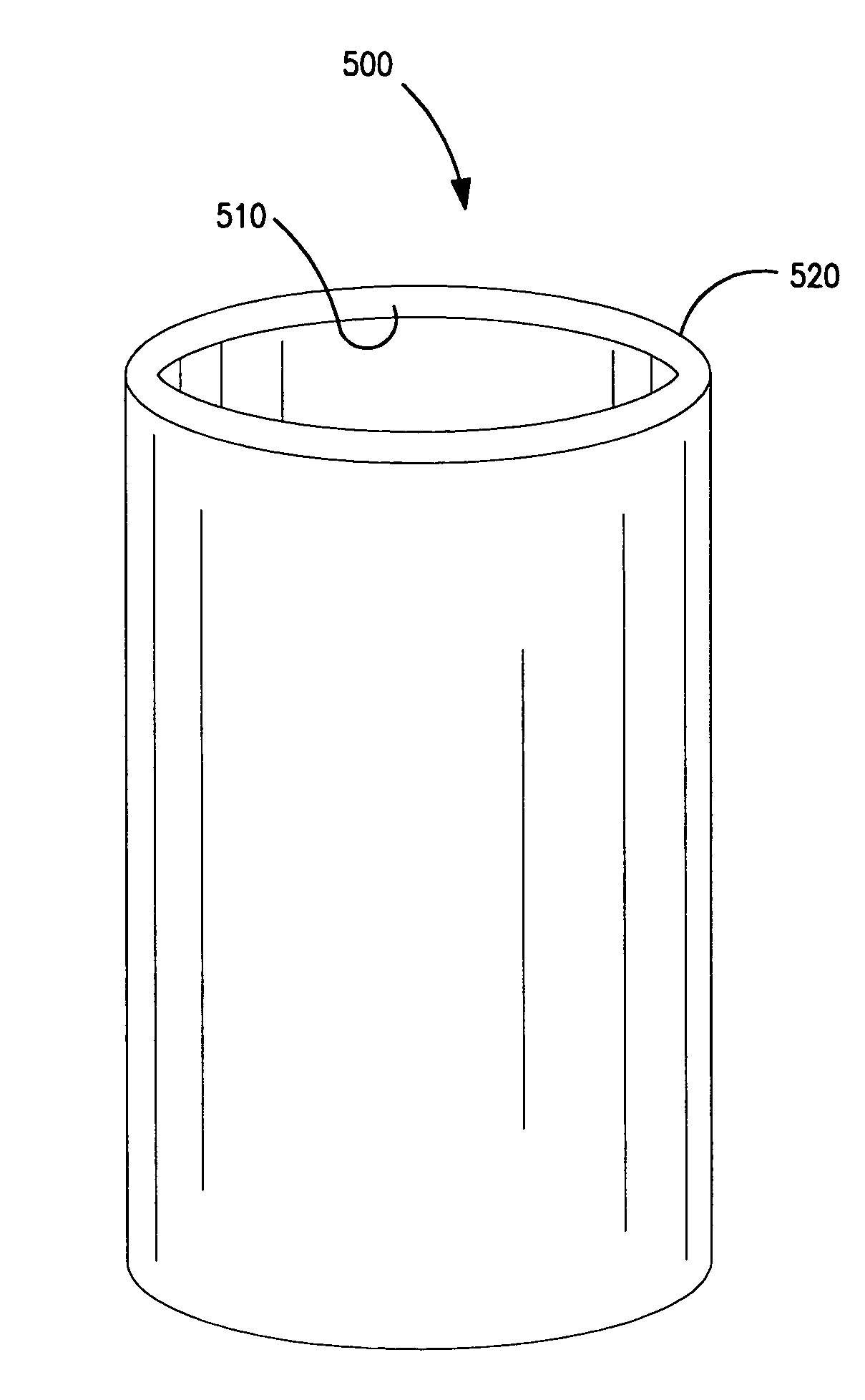
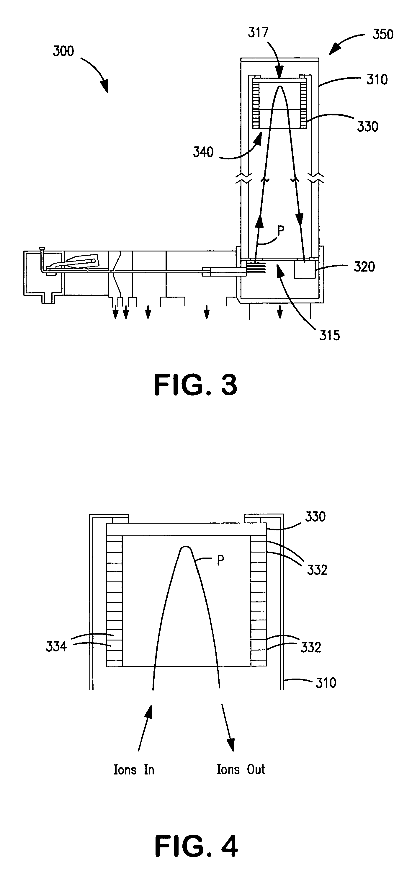
[0011]In response to the above needs, the present invention provides a reflectron lens for use in a reflectron analyzer. The reflectron lens comprises a tube having a continuous conductive surface along the length of the tube for providing an electric field interior to the tube that varies in strength along the length of the tube. The tube may comprise glass, and in particular, a glass comprising metal ions, such as lead, which may be reduced to form the conductive surface. In one configuration of the present invention, the conductive surface may be the interior surface of the tube. The tube may comprise a ce

Problems solved by technology

Such a lens assembly having many discrete components can be costly and complicated to fabricate.

Method used


Image

  • Conductive tube for use as a reflectron lens
  • Conductive tube for use as a reflectron lens
  • Conductive tube for use as a reflectron lens

Examples


examples

[0025]Reflectron lenses 600,650 of the present invention were fabricated from lead glass tubes of BURLE MCP-10 glass. The first reflectron lens 600 had the following physical dimensions: length of 3.862 inches; inner diameter of 2.40 inches; and, an outer diameter of 2.922 inches. The second reflectron lens 650 had the following physical dimensions: length of 6.250 inches; inner diameter of 1.200 inches; and, outer diameter of 1.635 inches.

[0026]The reflectron lenses 600,650 were placed in a hydrogen atmosphere at a pressure of 34 psi and a hydrogen flow of 40 l / m. The lenses 600, 650 were heated in the hydrogen atmosphere according to the following schedule. The temperature was ramped from room temperature to 200° C. over 3 hours. The temperature was then ramped to 300° C. over 1 hour, and then was ramped to 445° C. over 12.5 hours. The tube was held at 445° C. for 3 hours. The end to end resistance of the first reflectron lens 600 was measured to be 2.9×10⁹ ohms, and the end to en...


PUM


Abstract

A reflectron lens and method are provided. The reflectron lens comprises a tube having a continuous conductive surface along the length of the tube for providing an electric field interior to the tube that varies in strength along the length of the tube. The tube may comprise glass, and in particular, a glass comprising metal ions, such as lead, which may be reduced to form the conductive surface. The method includes a step of introducing a beam of ions into a first end of a dielectric tube having a continuous conductive surface along the length of the tube. The method further includes a step of applying an electric potential across the tube to create an electric field gradient that varies in strength along the length of the tube so the electric field deflects the ions to cause the ions to exit the tube through the first end of the tube.

Description

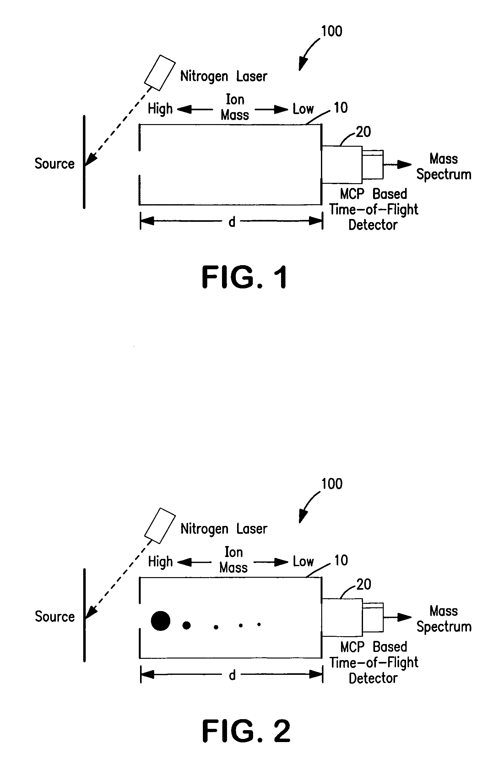
[0001]This application claims priority under 35 U.S.C. §119(e) from U.S. Provisional Application No. 60 / 455,801, filed Mar. 19, 2003, which is incorporated herein by reference.FIELD OF THE INVENTION[0002]The present invention relates generally to a dielectric tube for use as a reflectron lens in a time of flight mass spectrometer, and more particularly, to a glass tube having a conductive surface for use as a reflectron lens in a time of flight mass spectrometer.BACKGROUND OF THE INVENTION[0003]Time of Flight Mass Spectrometry (TOF-MS) is rapidly becoming the most popular method of mass separation in analytical chemistry. This technique is easily deployed, can produce very high mass resolution, and can be adapted for use with many forms of sample introduction and ionization. Unlike quadrupoles and ion traps, time of flight mass analyzers perform well at very high mass. Descriptions of described time of flight analyzers maybe found in Wiley and McLaren (Rec. Sci. Instrum., 26, 1150 (...

Claims


Application Information

Patent Timeline
IPC IPC(8): B01D59/44H01J3/16G01N27/62H01J49/00H01J49/04H01J49/16H01J49/40
CPCH01J49/405
Inventor LAPRADE, BRUCE
Owner PHOTONIS SCI INC
Learn More