
Apparatus for crosstalk compensation in a telecommunications connector

a technology of telecommunications connectors and accessories, applied in the direction of line-transmission details, waveguides, coupling device connections, etc., can solve the problems of only achieving limited success of crosstalk, and it is difficult to match this phase exactly

Active Publication Date: 2006-12-26
SIEMON
View PDF12 Cites 36 Cited by
  • Summary
  • Abstract
  • Description
  • Claims
  • Application Information

AI Technical Summary

Benefits of technology

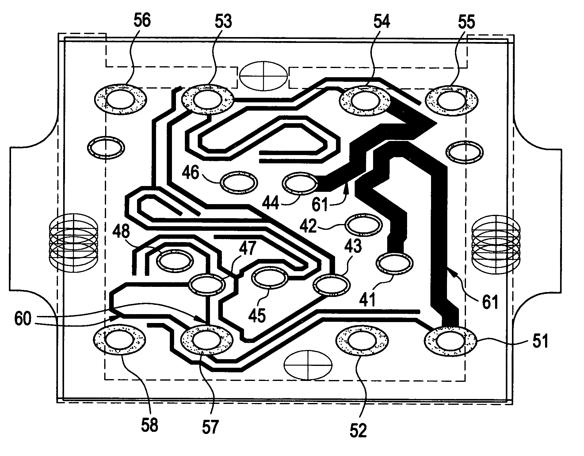
[0005]An embodiment of the invention is a printed circuit board providing crosstalk compensation. The printed circuit board includes first plated through holes for receiving a first connecting component and second plated through holes for receiving a second connecting component. A signal carrying trace transmits a signal from one of

Problems solved by technology

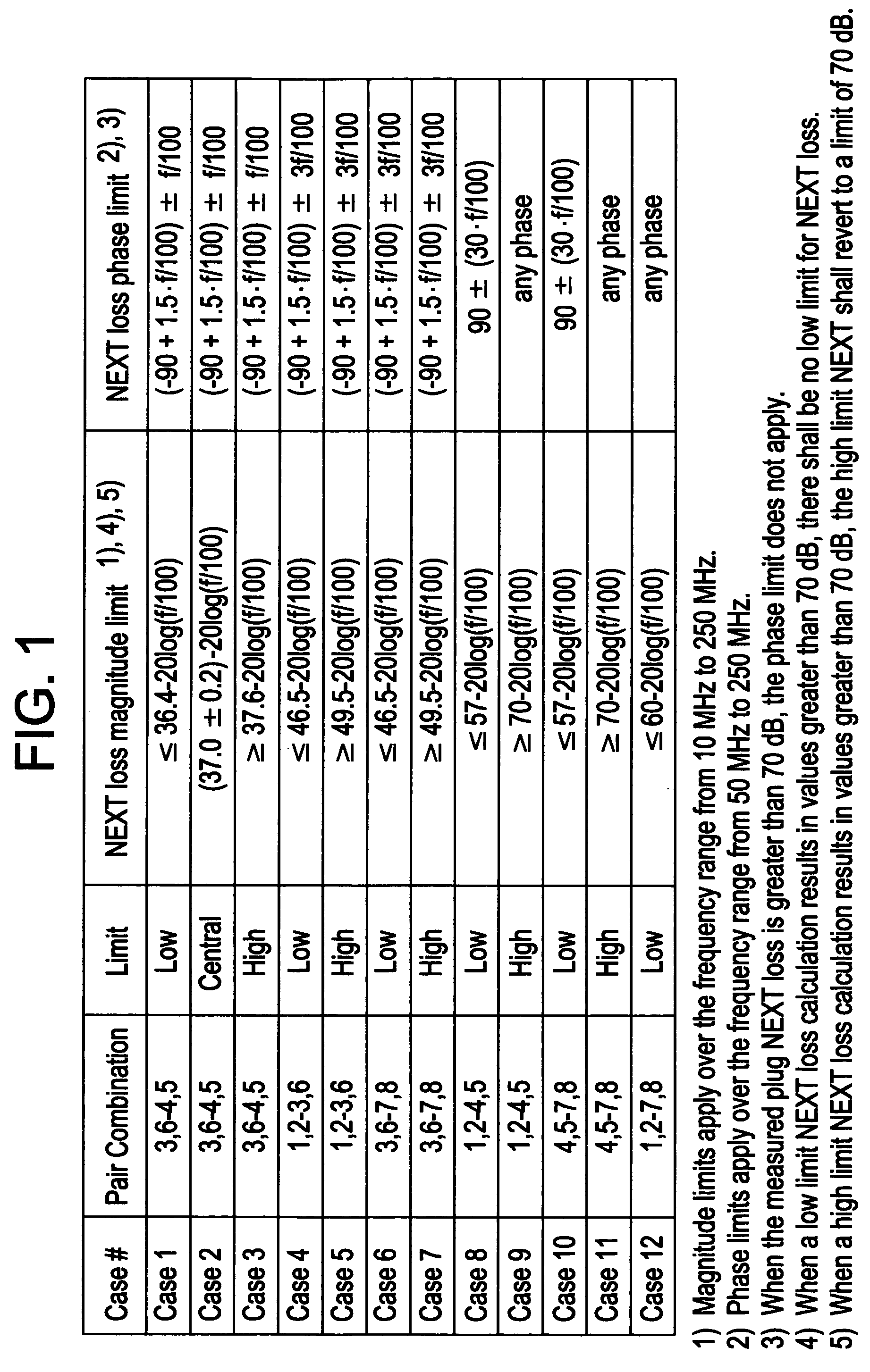
Standard compensating techniques involving reactive (e.g., inductive and capacitive) coupling to generate compensating crosstalk to cancel offending crosstalk can only achieve limited success due to the limits defined by the TIA and IEC in terms of the magnitude and phase for both NEXT and FEXT of qualification plugs.
In reality, it is difficult to match this phase exactly.

Method used


Image

  • Apparatus for crosstalk compensation in a telecommunications connector
  • Apparatus for crosstalk compensation in a telecommunications connector
  • Apparatus for crosstalk compensation in a telecommunications connector

Examples


Embodiment Construction

[0020]FIG. 3 is a side view of an exemplary telecommunications connector 10 designed to control phase of compensating crosstalk to improve transmission. The telecommunications connector 10 includes a plug 12 that is received in a first connecting component in the form of jack 14. In one embodiment of the invention, the plug is an RJ-45 jack carrying signals on a number (e.g., 4) twisted pairs of copper wire. The twisted pairs may be arranged in the plug in the T568A or T568B standard in which pair 4 / 5 is positioned between pair 3 / 6. Outlet 14 may similarly be an RJ-45 outlet and is mounted on a printed circuit board (PCB) 16. The PCB includes traces for carrying signals from the outlet 14 to a second connecting component in the form of wire termination block 18. The wire termination block may be a 110-type block as known in the art.

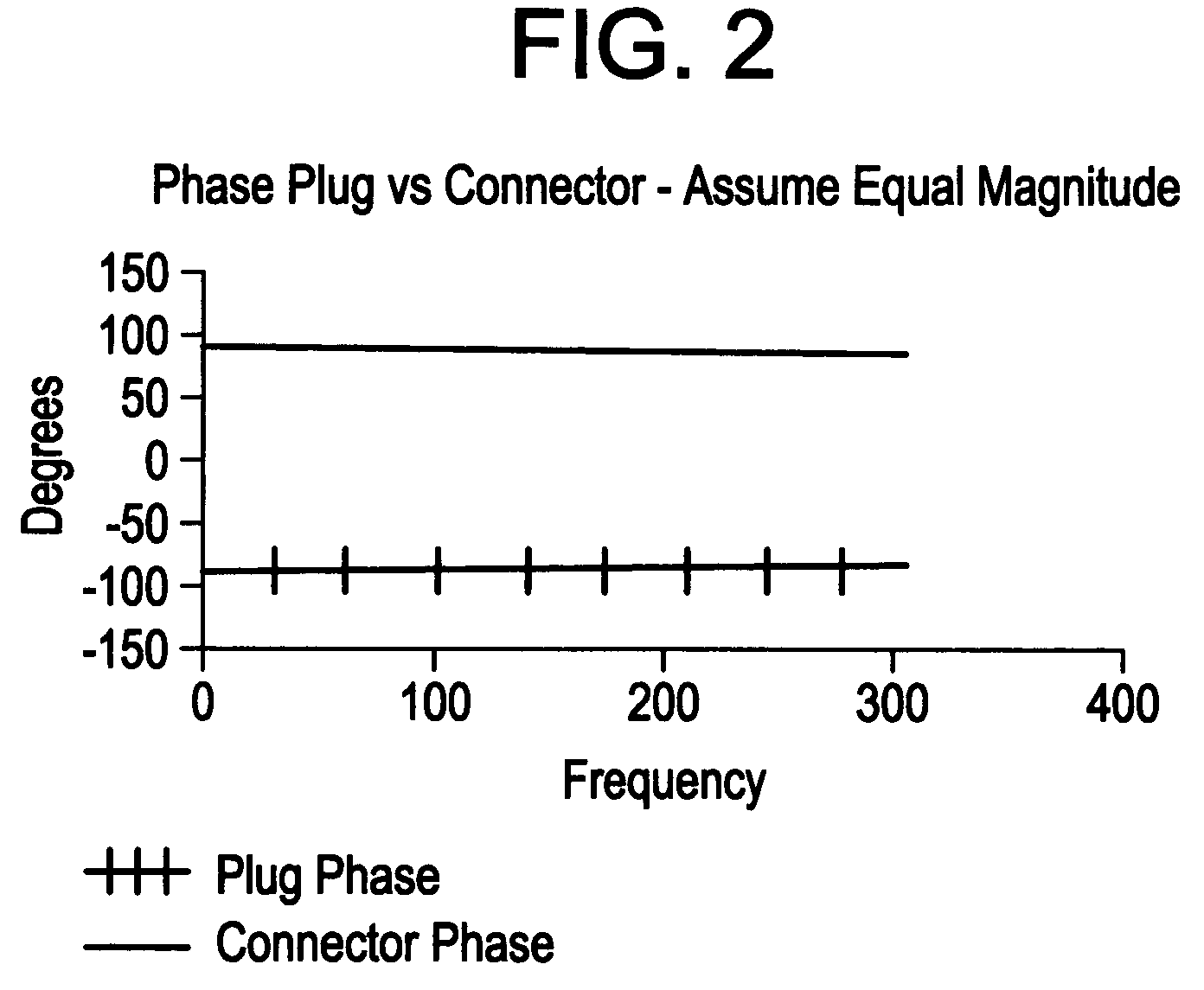
[0021]There is a phase shift due to the distance from the plug / jack interface to where the offending crosstalk is applied (e.g., PCB). It should be noted...


PUM


Abstract

A printed circuit board providing crosstalk compensation. The printed circuit board includes first plated through holes for receiving a first connecting component and second plated through holes for receiving a second connecting component. A signal carrying trace transmits a signal from one of the first plated through holes to one of the second plated through holes. A phase delay control trace is in electrical connection with the one of the first plated through holes. The phase delay control trace affects phase delay of the signal from the one of the first plated through holes to the one of the second plated through holes.

Description

CROSS-REFERENCE TO RELATED APPLICATIONS[0001]This application claims the benefit of U.S. provisional patent application Ser. No. 60 / 427,985 filed Nov. 20, 2002, the entire contents of which are incorporated herein by reference.BACKGROUND OF THE INVENTION[0002]The invention relates to telecommunications connectors and methods and apparatus for controlling signal delay in telecommunications connectors to improve NEXT, FEXT and return loss in terms of magnitude and upper frequency limits of transmission components and products. Near end crosstalk (NEXT), far end crosstalk (FEXT) and return loss limit tranmission rates of telecommuncations (e.g., voice, data, etc) connectors. Standard compensating techniques involving reactive (e.g., inductive and capacitive) coupling to generate compensating crosstalk to cancel offending crosstalk can only achieve limited success due to the limits defined by the TIA and IEC in terms of the magnitude and phase for both NEXT and FEXT of qualification plu...

Claims


Application Information

Patent Timeline
IPC IPC(8): H05K7/06H04B3/32H05K1/02
CPCH05K1/0228H05K1/0248H05K2201/09727H05K2201/10189H05K2201/09781H05K2201/0979H05K2201/09736
Inventor CELELLA, BRIANPAGLIARULO, VITOMULLIN, DANIEL
Owner SIEMON
Learn More