
Both-side grinding method and both-side grinding machine for thin disc work

a technology of both-side grinding and thin disc, which is applied in the direction of grinding drives, manufacturing tools, lapping machines, etc., can solve the problems of the difference in the amount of wear between the grinding surfaces of both grinding wheels, the deviation of the position of the grinding surface from the predetermined initial or desired position, and the wear of the grinding surface of each grinding wheel with the lapse of time, etc., to achieve excellent parallelism and flatness, work is free of bending

Inactive Publication Date: 2006-12-19
KOYO MASCH IND CO LTD
View PDF10 Cites 19 Cited by
  • Summary
  • Abstract
  • Description
  • Claims
  • Application Information

AI Technical Summary

Benefits of technology

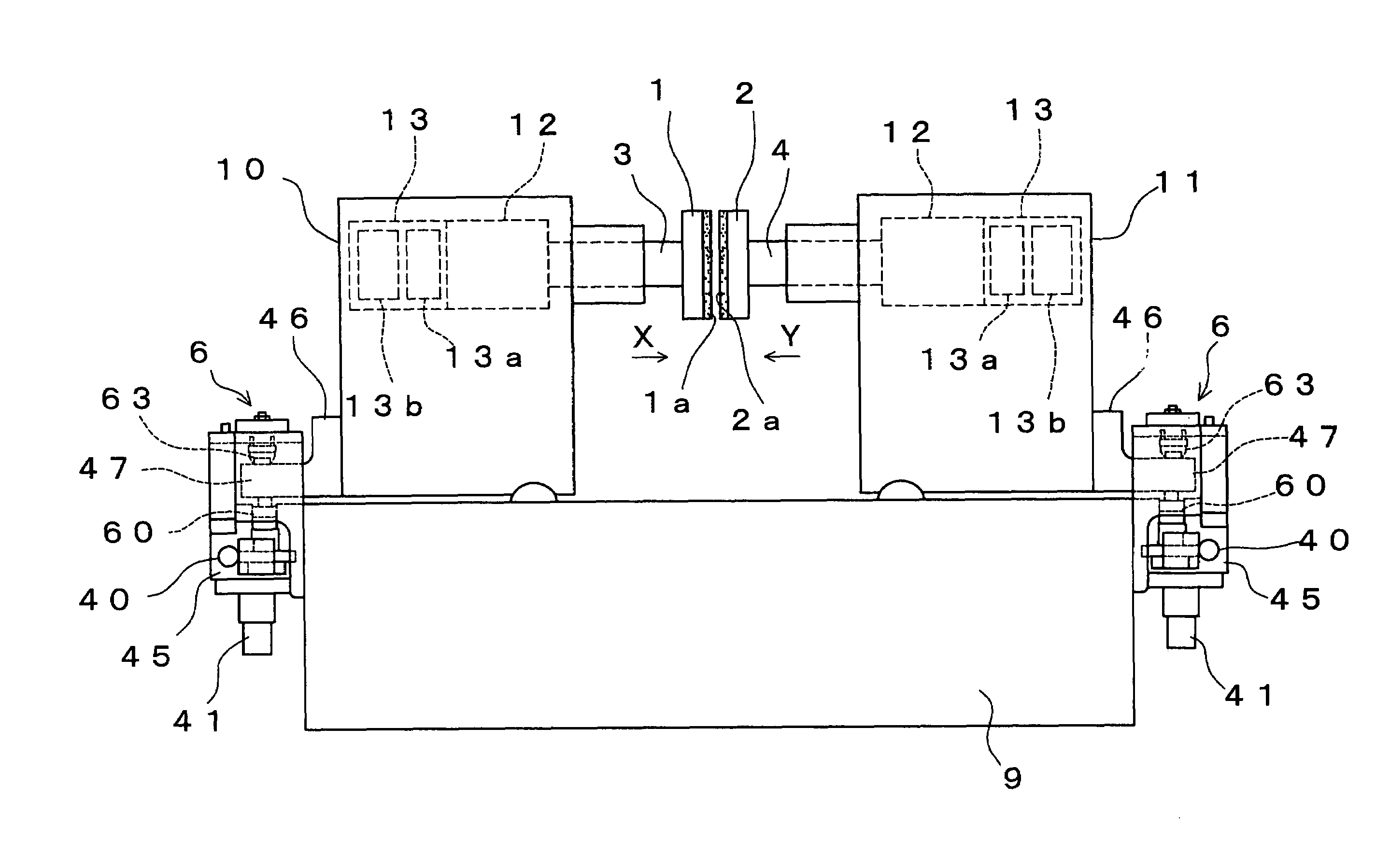
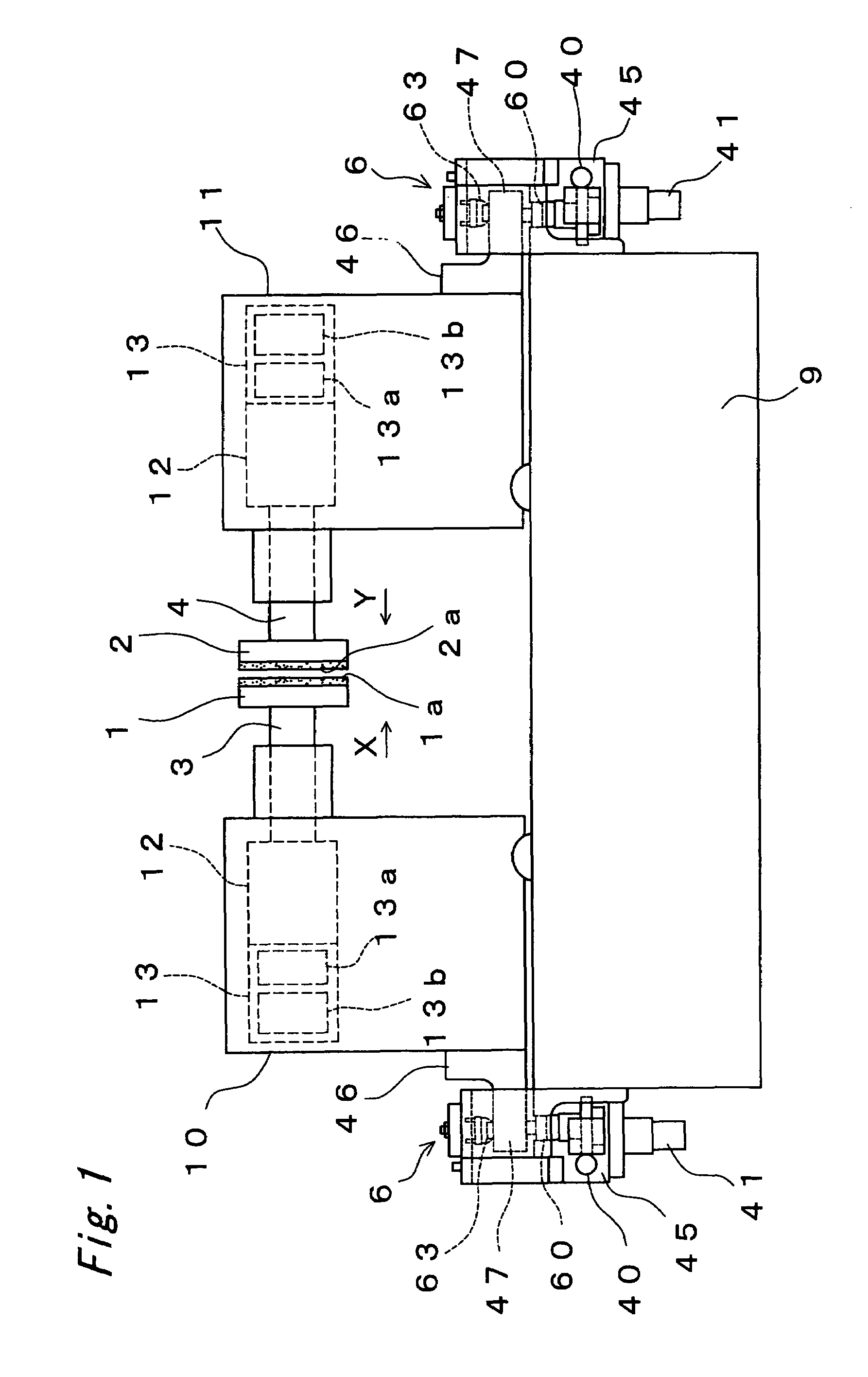
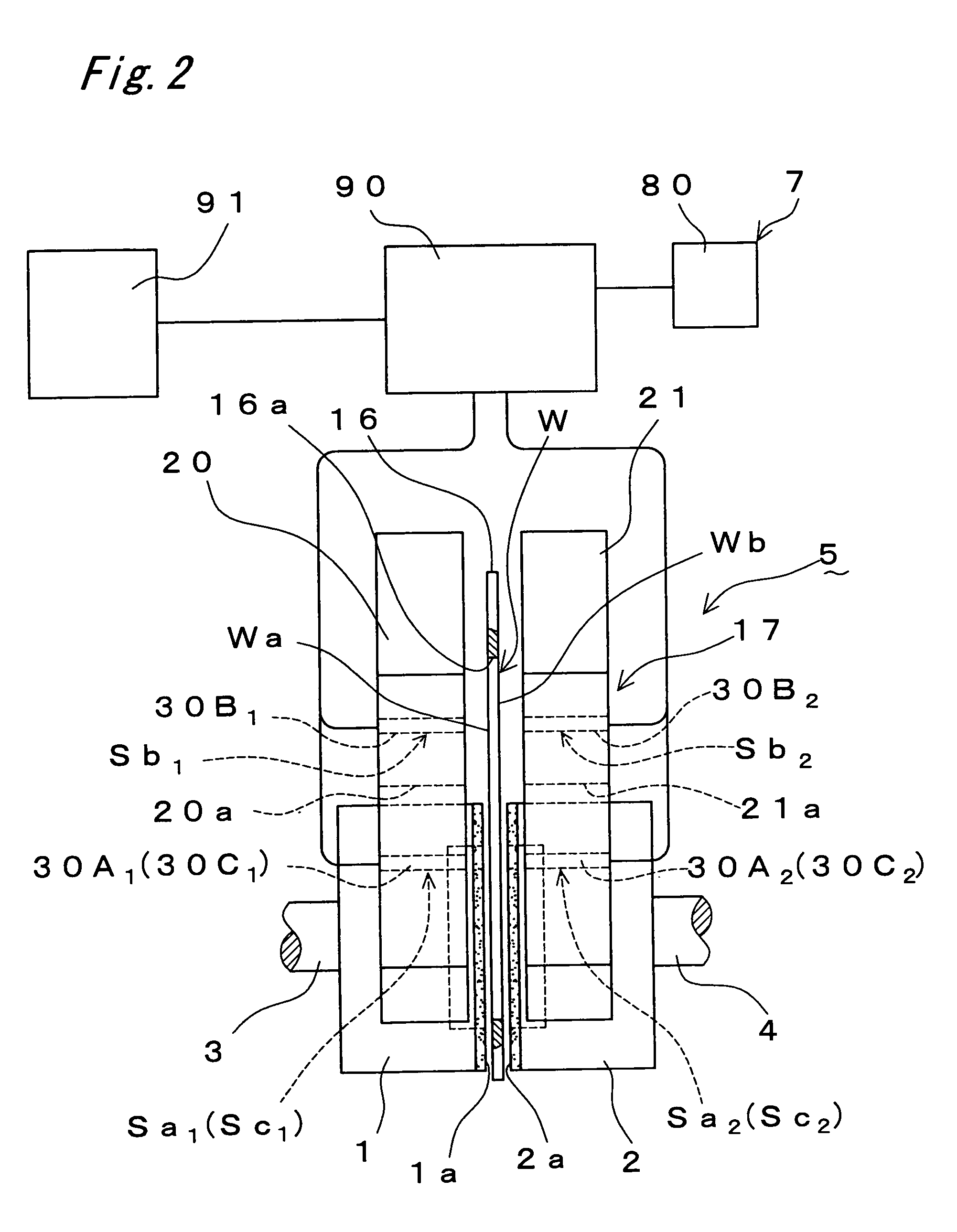
[0019]In this case, when the feeding operation of the grinding wheel is completed, the respective distances from the specified reference position to the surface and back of the work are measured at three points at least by using a non-contact type distance sensor, and the amount of deformation of the work is detected from the results of measurement at three points at least. Also, in case the calculated amount of deformation exceeds the specified value, the grinding wheel is adjusted in accordance with the amount of deformation so that the work is flat without deformation when the feeding operation of the grinding wheel is completed, and thereby, it is possible to keep the grinding wheels in correct positions (correct axial direction and tilt) and to obtain work being free from bending and excellent in parallelism and flatness.

Problems solved by technology

As the pair of grinding wheels repeat grinding operation, the grinding surface of each grinding wheel wears with the lapse of time, and there arises a difference in the amount of wear between the grinding surfaces of both grinding wheels.
As a result, the positions of these grinding surfaces gradually become deviated from the predetermined initial or desired positions.
As a result, the work after grinding will be bent and there may arise a problem of its lowering in flatness and the like.
Also, even in case of defective tilt of the grinding wheel spindle due to secular change of component parts of the machine or external factors such as thermal displacement, the work will bend during grinding operation, and there arises a problem the same as mentioned above.
However, in the above grinding method, it is unable to detect the defective tilt of the grinding wheel spindle, and therefore, the problem of bending of the work result therefrom cannot be solved.

Method used


Image

  • Both-side grinding method and both-side grinding machine for thin disc work
  • Both-side grinding method and both-side grinding machine for thin disc work
  • Both-side grinding method and both-side grinding machine for thin disc work

Examples


embodiment 2

[0102]In embodiment 1, the moving adjustment of grinding wheels 1, 2 is made after completion of grinding of work W, but in this embodiment, the moving adjustment of grinding wheels 1, 2 is performed during grinding of work W as described in the following.

[0103]That is, in this embodiment, same as in the case of embodiment 1, the ideal distance value L0 for distance values La, Lb, Lc is stored in the initial state, and the tilt of grinding wheel 1, 2 is corrected in accordance with the distance values La, Lb, Lc while monitoring each distance value La, Lb, Lc at the time of spark-out of grinding wheel 1, 2.

[0104]That is, when the distance value is La≠Lc, wheel position control unit 8 first makes the moving correction of horizontal tilt of grinding wheel spindles 3, 4 (in case La=Lc from the beginning, the moving correction is not needed) until the distance value La=Lc.

[0105]Next, the vertical tilt of grinding wheels 3, 4 is corrected to make it as shown in FIG. 8 until the distance ...


PUM

PropertyMeasurementUnit
distanceaaaaaaaaaa
angleaaaaaaaaaa
speedaaaaaaaaaa

Abstract

Detecting the deviation of the grinding wheel position from the amount of work deformation after grinding, and correctly adjusting the grinding wheel position, it provides both-side grinding techniques for making the work excellent in flatness and parallelism. When the feeding operation of grinding wheels (1,2) is completed, the distances from hydrostatic pads (20, 21) to the surface and back of work (W) are measured at three points, and the deformation amount of work (W) is detected from the results of measurement at the three points by using air gauge sensors (Sa, Sb, Sc), and in case the calculated amount of deformation exceeds the specified value, the moving adjustment of grinding wheels (1, 2) is performed in accordance with the amount of deformation so that work (W) is flat without deformation when the feeding operation of grinding wheels (1, 2) is completed.

Description

TECHNICAL FIELD[0001]The present invention relates to a both-side grinding method and a both-side grinding machine for thin disc work, and more particularly, it relates to grinding techniques for simultaneously grinding the surface and back sides of a thin disc work such as a semiconductor wafer or the like by means of a pair of grinding wheels.BACKGROUND ART[0002]Conventionally, as a both-side grinding method for grinding the surface and back sides of such thin disc work (hereinafter called work), the one disclosed in Japanese Laid-open Patent H11-198009 is available.[0003]In this grounding method, the work is disposed between a pair of cup type grinding wheels rotating at a high speed so that the outer periphery of the work intersects the outer periphery of the grinding surface of the grinding wheel and the center of the work is positioned within the annular grinding surface of the grinding wheel, and the work portion protruded radially outwardly from the outer periphery of the gr...

Claims


Application Information

Patent Timeline
Patent Type & Authority Patents(United States)
IPC IPC(8): B24B49/04B24B7/16B24B7/17B24B7/22B24B9/14B24B37/04B24B37/08B24B49/02B24B49/08B24B49/10
CPCB24B7/16B24B7/17B24B7/228B24B9/148B24B37/08B24B49/02B24B49/08
Inventor OKURA, KENJI
Owner KOYO MASCH IND CO LTD
Learn More