Cylindrical roller bearing

a cylindrical roller bearing and roller bearing technology, applied in the direction of attachable milling devices, mechanical equipment, manufacturing tools, etc., can solve the problems of increased prone to heat generation and wear, and the thermal expansion of the spindle is relatively large, and the effect of reducing the cost of the spindle apparatus

Inactive Publication Date: 2006-12-19
NTN CORP
View PDF29 Cites 18 Cited by
  • Summary
  • Abstract
  • Description
  • Claims
  • Application Information

AI Technical Summary

Benefits of technology

[0024]More specifically, an object of the present invention is to provide a cylindrical roller bearings in which contact surface pressure between cylindrical rollers and collars, particularly before the skew angle of the cylindrical rollers reaches its maximum level θMAX, is reduced, whereby heat generation and wear in contact portions are reduced, and which is thereby made suitable for high speed applications.
[0048]According to the present invention, there is provided a cylindrical roller bearing which generates less heat during high rotation and thus is more suitable for high speed applications.

Problems solved by technology

On the other hand, more heat is generated during high speed rotation in these bearings as compared to ball bearings, and the portions where the cylindrical rollers and the collars make sliding contact are particularly susceptible to heat generation and wear.
This can cause high friction resistance in the sliding contact portions, resulting in heat generation and wear.
Alternatively, a sliding member such as a ball bush may be interposed between the outer ring and the housing may lead to creep and wear in the contact portions therebetween particularly when the rotation speed of the spindle is high.
In the latter construction, the provision of additional sliding members such as ball bushes results in larger numbers of components and assembling steps.
Furthermore, the problem common to both constructions is that costs tend to be high because of the use of angular ball bearings which require two bearings in combination and which often use ceramic balls to be suitable for higher speed applications.
On the other hand, cylindrical roller bearings have the problem that more heat is generated during high speed rotation as compared to angular ball bearings.
In a spindle apparatus with this drive system, however, there tends to be a difference in the temperature between the spindle and the housing due to the built-in motor which generates heat, because of which the negative clearances in the rolling bearings are increased as compared to an apparatus with the belt drive system, i.e., they are operated in a pre-loaded condition.
There is also the problem that thermal expansion of the spindle in the axial direction tends to be large because of the long span between the rolling bearings on the front side and on the rear side.

Method used


Image

  • Cylindrical roller bearing
  • Cylindrical roller bearing
  • Cylindrical roller bearing

Examples


Embodiment Construction

[0068]Preferred embodiments of the present invention will be hereinafter described with reference to the accompanying drawings.

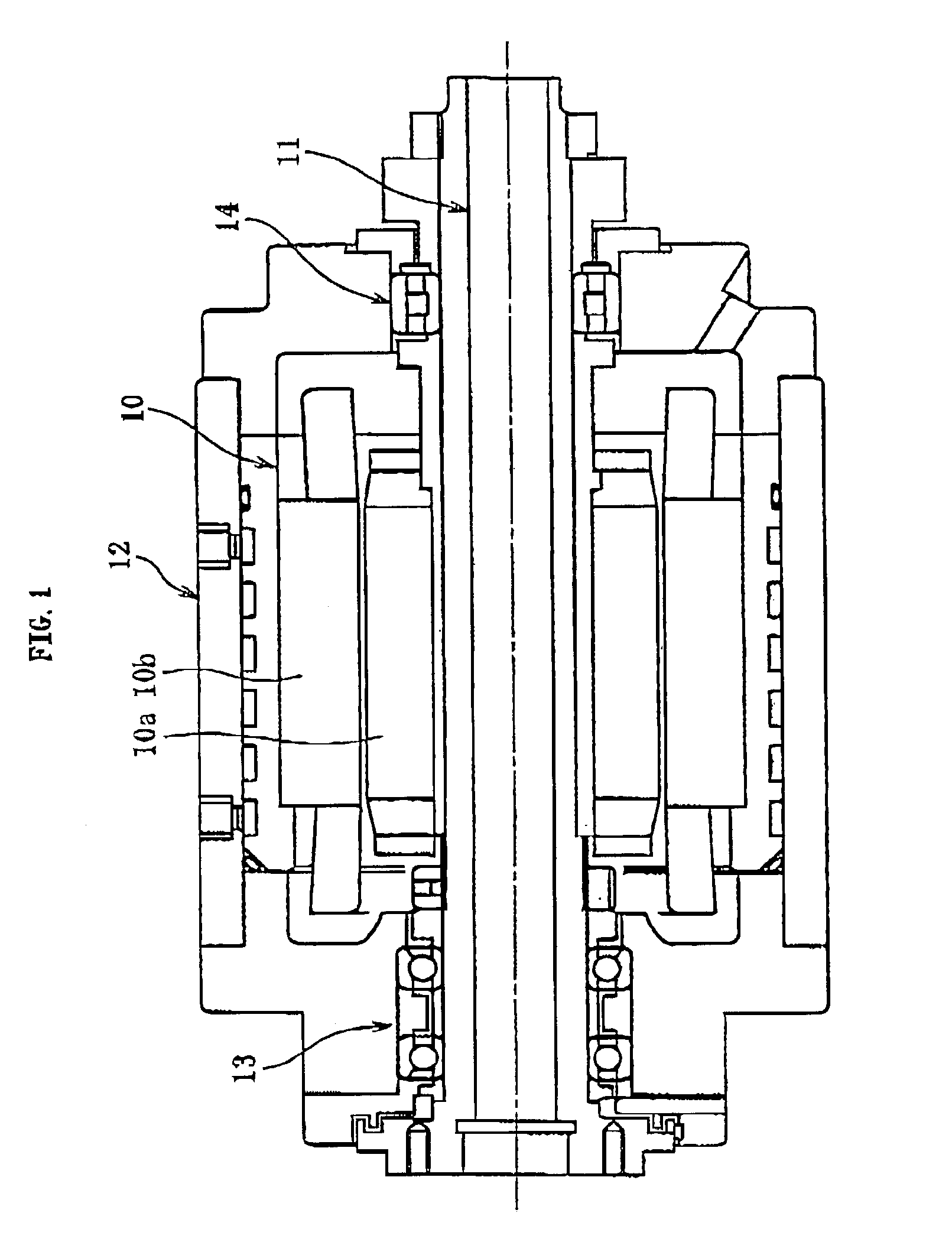
[0069]FIG. 1 shows one example of the structure of a spindle apparatus in a machining tool such as a machining center, grinder and the like. The illustrated spindle apparatus is a built-in type, in which a spindle 11 is rotated at high speed by a built-in motor 10. The motor 10 is disposed in an axially central portion of the spindle apparatus and made up of a rotor 10a mounted on the outer periphery of the spindle 11 and a stator 10b mounted on the inner periphery of the housing 12. Electric current applied to the stator 10b creates an excitation force between the stator 10b and the rotor 10a, whereby the spindle 11 is rotated at high speed.

[0070]The rotating spindle 11 is rotatably supported with respect to the housing 12 by roller bearings respectively arranged at either end of the motor 10, i.e., the front side or tool side and at the rear side opposite ...


PUM

PropertyMeasurementUnit
curvature radiusaaaaaaaaaa
critical skew angle θTaaaaaaaaaa
skew angleaaaaaaaaaa

Abstract

Contact surface pressure P increases rather drastically in proportion to skew angle θ within the range of 0<θ≦θT, but because the critical skew θT is restricted to be small, the contact surface pressure P changes in a low range below a certain level P0 at which wear occurs in contact portions. Thus restricting the critical skew angle θT to a small angle reduces the contact surface pressure P and suppresses heat generation and wear in the contact portions.

Description

BACKGROUND OF THE INVENTION [0001]1. Field of the Invention[0002]The present invention relates to a cylindrical roller bearing suitable for supporting a shaft in high speed installations such as machining tools, jet aircraft engines, and gas turbines.[0003]2. Description of the Related Art[0004]Spindle apparatuses of machining tools such as machining centers, CNC lathe turning machines, milling machines, and the like are often operated at high speed for the sake of better machining efficiency and higher precision of work, and the recent trend is toward further increase in the speed of spindle rotation.[0005]Generally, in a spindle apparatus of a machining tool, the spindle is supported rotatably relative to the housing by rolling bearings respectively disposed at the front side or tool side and at the rear side opposite the tool side. Lubrication of the rolling bearings is achieved by any of oil mist lubrication, air / oil lubrication, jet lubrication, and grease lubrication, in accor...

Claims


Application Information

Patent Timeline
Patent Type & Authority Patents(United States)
IPC IPC(8): F16C19/00B23Q1/40B23Q1/26F16C19/26F16C33/46F16C33/58
CPCF16C19/26F16C33/4635F16C33/58F16C33/467Y10T409/309352F16C19/225F16C33/34F16C33/585F16C2322/39F16C2240/40F16C2240/70F16C2240/42F16C2208/36F16C19/49
Inventor KOYAMA, MINEOTORISAWA, HIDETOTAKIUCHI, HIROSHIMIZUTANI, MAMORU
Owner NTN CORP
Why Eureka
Try Eureka