
Anti-armor multipurpose and chemical energy projectiles

a technology of chemical energy and projectiles, applied in the direction of ammunition projectiles, projectiles, weapons, etc., can solve the problems of deeper penetration damage and impartition of more, and achieve the effect of increasing the lethality of mp and ce warhead projectiles and more kinetic energy

Inactive Publication Date: 2006-12-19
ARMY US SEC THE
View PDF14 Cites 12 Cited by
  • Summary
  • Abstract
  • Description
  • Claims
  • Application Information

AI Technical Summary

Benefits of technology

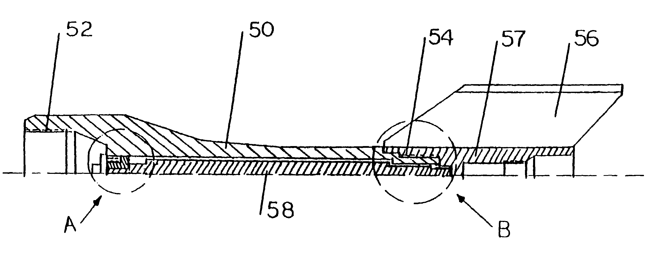
[0012]More particularly, the present invention increases the lethality of MP and CE warhead projectiles, by utilizing and converting the tail fin boom into a tube carrying an added high-density KE penetrator rod warhead. The penetrator rod is positioned to impact the target after the detonation of the front main CE or MP warhead. The release mechanism for the added KE penetrator rod is the forward momentum energy released by the stoppage of the main carrier projectile upon impact with the target. Upon impact, the added penetrator slips forward, following into the hole created by the MP / CE liquid metal jet, imparting more kinetic energy and causing deeper penetration damage to the target.

Problems solved by technology

Upon impact, the added penetrator slips forward, following into the hole created by the MP / CE liquid metal jet, imparting more kinetic energy and causing deeper penetration damage to the target.

Method used


Image

  • Anti-armor multipurpose and chemical energy projectiles
  • Anti-armor multipurpose and chemical energy projectiles
  • Anti-armor multipurpose and chemical energy projectiles

Examples


Embodiment Construction

[0024]FIG. 4 shows an anti-armor projectile according to the present invention. The projectile includes a tail fin boom 50, front threads 52, rear threads 54, fins 56, and a fin set piece 57. The tail fin boom has a fin-end (first end), and a main body end (second end). An added kinetic energy rod warhead 58 is housed in a long central hole provided in the tail fin boom itself. This added rod warhead is shown in FIG. 5. The rod warhead 58 may be of circular cross section as given by section E—E, among other possible shapes. The rod warhead is usually made of high-density material (e.g., tungsten or depleted uranium). The embodiment of FIG. 5 shows the rod with stepped-down ends 60, 62, 64, and 66. Reduced size ends are needed to arrange for the support, resting, and attachment of the added warhead to the main carrier body of the projectile. The front-step 60 and rear-step 62 are non-circular as shown by sections C—C and G—G of FIG. 5. The steps 64 and 66 are depicted as being of cir...


PUM


Abstract

An anti-armor projectile has a tail fin boom having an inner hollow area. A warhead made of high density materials is disposed in the hollow area to serve as a kinetic-energy penetrator that is released upon impact to increase the lethality of the anti-armor projectile.

Description

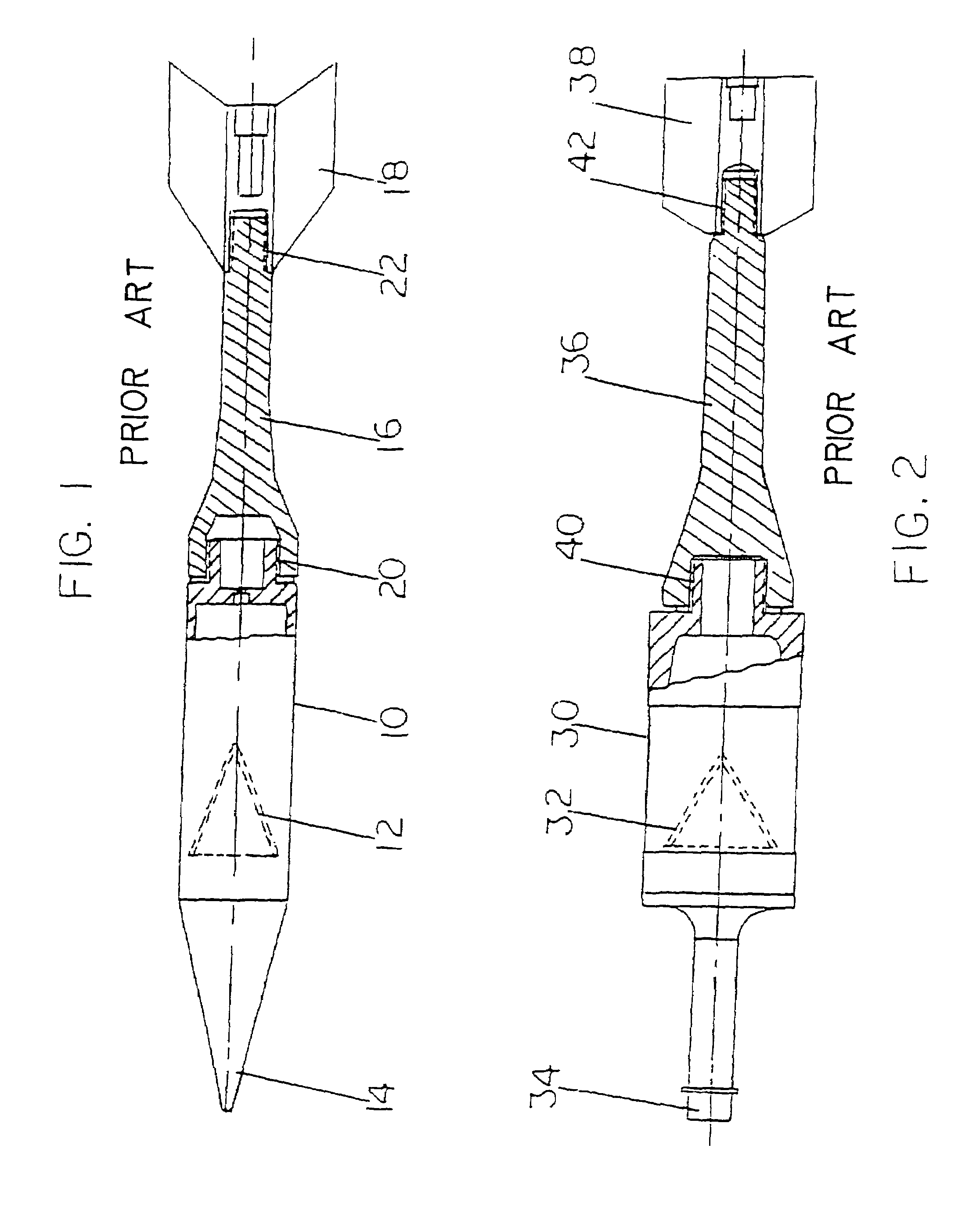
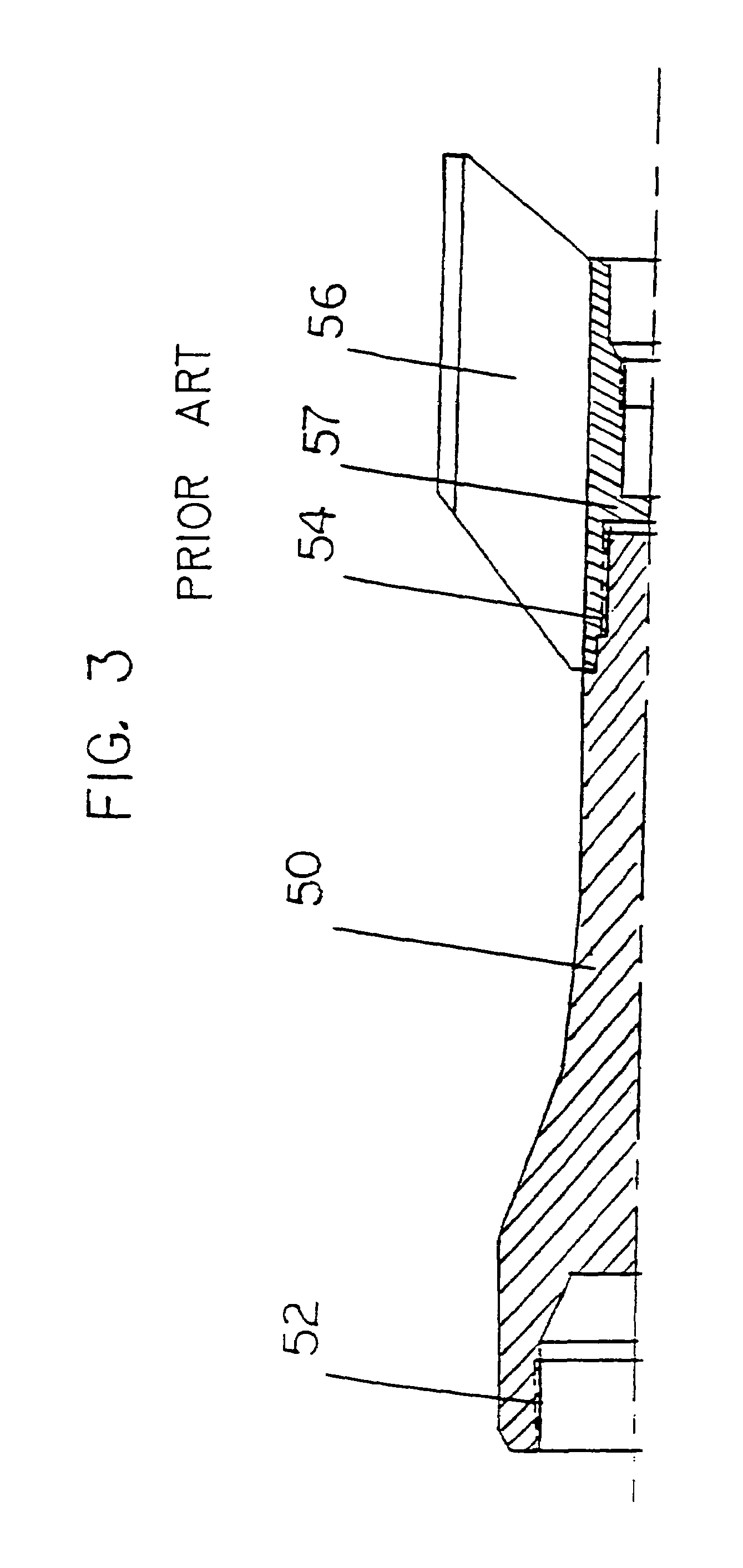
GOVERNMENT INTEREST[0001]The invention described herein may be manufactured and used by or for the Government of the United States of America for government purposes without the payment of any royalties therefor.BACKGROUND OF THE INVENTION[0002]1. Field of the Invention[0003]This invention relates to an armor-penetrating tandem-projectile.[0004]2. Description of the Related Art[0005]Certain types of chemical energy (CE) warheads are formed by cone-shaped metallic liners which are later transformed into a metallic liquid jet by an explosive shaping charge carried on board the projectile. The CE warhead must be activated very near the target (about 1–2 meters) so that the formed metallic jet does not break up. Also, a spacer / spike in front of the liner provides a very short time delay needed to form the jet, when an impact fuse is mounted on the tip of that spacer spike. Alternatively, a proximity fuse may be used instead of the impact fuse if the intended target is moving (as in heli...

Claims


Application Information

Patent Timeline
Patent Type & Authority Patents(United States)
IPC IPC(8): F42B10/06F42B12/06F42B12/16
CPCF42B10/06F42B12/06F42B12/16
Inventor MIKHAIL, AMEER G.
Owner ARMY US SEC THE
Learn More