
Method of making a diffuser assembly

a technology of diffuser assembly and assembly method, which is applied in the field of diffuser assembly, can solve the problems of diffuser assembly including components, metals and/or organic plastic components in the diffuser assembly, and eventually failing, and the diffuser assembly, while superior to prior art diffuser assembly, is also subject to some limitations

Active Publication Date: 2006-11-28
FILTROS
View PDF25 Cites 19 Cited by
  • Summary
  • Abstract
  • Description
  • Claims
  • Application Information

AI Technical Summary

Benefits of technology

"The present invention provides an all-ceramic diffuser assembly that includes a diffuser element and a base. The diffuser element is made of a porous ceramic material, while the base is made of a non-porous ceramic material. The base has a conduit for directing a stream of gas or liquid that can diffuse through the diffuser element. The invention also provides a method for making the diffuser assembly by positioning the diffuser element, a separator, and a conduit-former in a mold and injecting a slurry to form the non-porous ceramic material. The technical effects of the invention include improved durability and reliability of the diffuser assembly, as well as improved stability and control of the gas or liquid diffusion process."

Problems solved by technology

One disadvantage of this construction, however, is that the diffuser assembly includes components that are formed of materials that are vulnerable, over a period of time, to the corrosive effects of the environment it is being used in.
Ozone gas is the highly corrosive, and over time the metals and / or organic plastic components in the diffuser assembly eventually fail due to corrosion damage.
This diffuser assembly, while superior to prior art diffuser assemblies, is also subject to some limitations.
The bond or joint formed between the diffuser element and the housing using the cement is strong, but it is also brittle.
In some situations, this bond can break when the diffuser assembly is packaged, shipped, unpacked or installed.
In addition, vibrations caused by the gas supply equipment can also jar the diffuser assembly enough to cause the cement joint to fail.
While this material is more resistant to the corrosive effects of ozone gas than some other materials, it still does not have the resistance and durability provided by inorganic ceramic materials.

Method used


Image

  • Method of making a diffuser assembly
  • Method of making a diffuser assembly
  • Method of making a diffuser assembly

Examples


Embodiment Construction

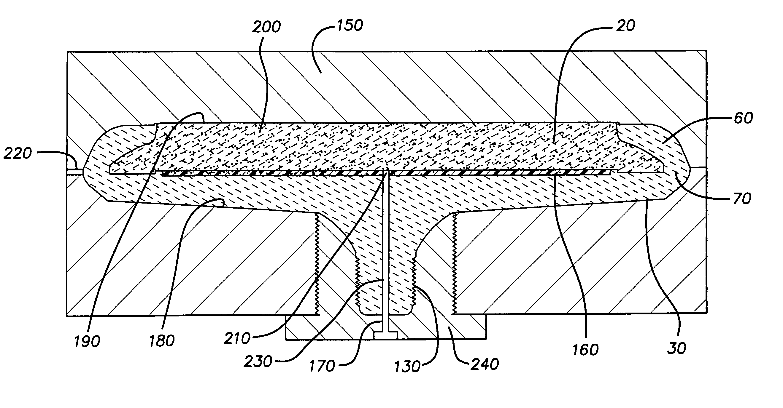
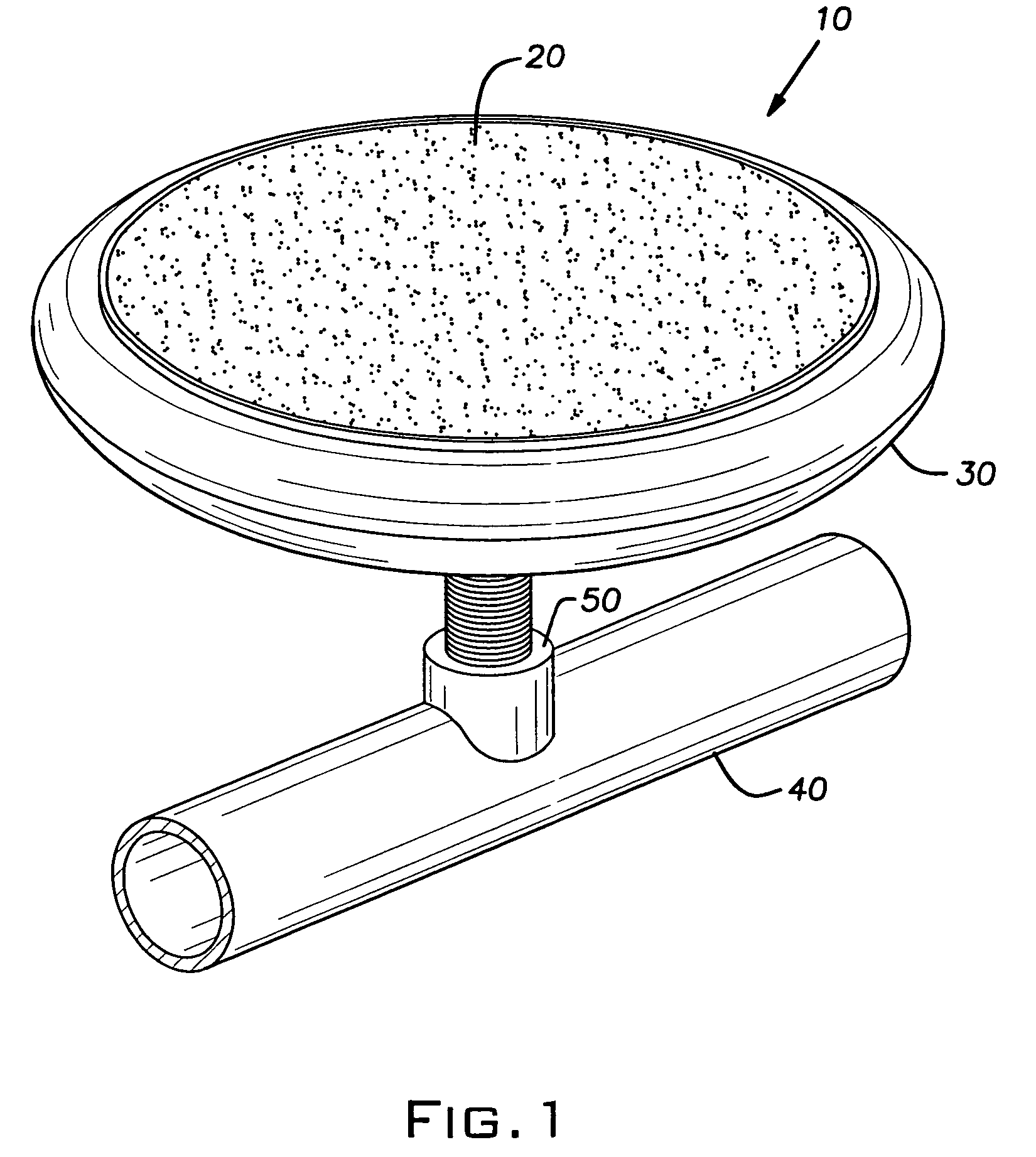
[0022]Referring more particularly to FIG. 1, there is shown a perspective view of a preferred embodiment of a diffuser assembly 10 according to the invention. The diffuser assembly 10 is adapted for immersion in a liquid or semi-liquid medium. Gas or liquid pumped under pressure into a cavity within the diffuser assembly diffuses through a porous ceramic diffuser element, forming minute bubbles or microbubbles that disperse into the liquid or semi-liquid medium.

[0023]The diffuser assembly 10 is particularly adapted for use in systems where highly corrosive and / or reactive gases (e.g., ozone) or liquids need to be dispersed in liquid or semi-liquid mediums. It is well known that ozone provides an efficient reactant for purifying water in standard water treatment processes. However, the effective mixing of the ozone gas in the water is essential due to ozone's relatively low solubility in water. In such applications, the diffuser assembly 10 according to the invention can be attached ...


PUM

PropertyMeasurementUnit
outer dimensionsaaaaaaaaaa
perimeteraaaaaaaaaa
circular shapeaaaaaaaaaa

Abstract

The present invention provides an all-ceramic diffuser assembly that includes a diffuser element formed of a porous ceramic material and a base formed of a non-porous ceramic material. The base includes a peripheral undercut shoulder portion that overlaps a perimeter edge of the diffuser element to sealingly connect the diffuser element to the base. A conduit is formed in a fitting portion of the base for directing a stream of gas or liquid that is capable of diffusing through the diffuser element into a chamber formed between an inner surface of the diffuser element and a floor portion of the base. The present invention also provides a method of forming the diffuser assembly.

Description

CROSS-REFERENCE TO RELATED APPLICATIONS[0001]This is a continuation-in-part of application Ser. No. 10 / 627,339 filed Jul. 25, 2003, now U.S. Pat. No. 6,889,964.BACKGROUND OF THE INVENTION[0002]1. Field of Invention[0003]The present invention relates to a diffuser assembly for finely dispersing gases or liquids and a method of making the same.[0004]2. Description of Related Art[0005]Diffuser assemblies are used in a variety of application to finely disperse gases or liquids into other liquids. Ozone gas, for example, is sometimes diffused through a diffuser assembly into water for the purpose of purifying the water. In wastewater treatment applications, wastewater is collected in a large pond, tank or basin. A manifold structure that includes a series of supply pipes arranged in an array is typically installed near the bottom of the pond, tank or basin. One or more diffuser assemblies are connected to the supply pipes at various locations to provide a substantially uniform pattern of...

Claims


Application Information

Patent Timeline
Patent Type & Authority Patents(United States)
IPC IPC(8): B28B1/30B01F3/04
CPCB01F3/0412B01F3/04262B01F2003/04276B01F2003/04297B01F2003/0439B01F23/2311B01F23/23125B01F23/231262B01F23/23123
Inventor WAY, PHILIP S.BRAGG, BILLY RAY
Owner FILTROS
Learn More