Optical fiber wiring sheet and method of manufacturing same
a technology of optical fiber and wiring sheet, which is applied in the direction of optical waveguide light guide, glass optical fibre, instruments, etc., can solve the problems of poor production efficiency, inability to split the desired number of cores, and the production process of these optical fiber tape cores is difficult, so as to achieve the effect of preventing congestion of coated optical fibers in optical circuit devices, facilitating effective installation and maintenance/inspection, and simplifying connection patterns
- Summary
- Abstract
- Description
- Claims
- Application Information
AI Technical Summary
Benefits of technology
Problems solved by technology
Method used
Image
Examples
example 1
[0097]An optical fiber wiring sheet with a branching structure was produced according to the process illustrated in FIG. 22. This application apparatus comprised a single-axis control robot (10) and a material feeding apparatus (not shown). The single-axis control robot had a substrate with two-dimensional plane (5) on which to place coated optical fibers. It also had a ball-screw shaft (12) extending in the longitudinal direction, with a drive motor (13) provided on one end of the ball-screw shaft, while the other end was supported by a bearing (14). This ball screw engaged with a movable unit (15) by means of threads, and on this movable unit a needle (16) vertically movable to supply material was installed perpendicular to the stage surface. The needle was connected to the material feeding apparatus via a flexible rubber tube (not shown). The tip of the needle (16) had a flat bottom, where a forming jig (17) of 40 mm in width, 30 mm in length and 40 mm in height could be attached...
example 2
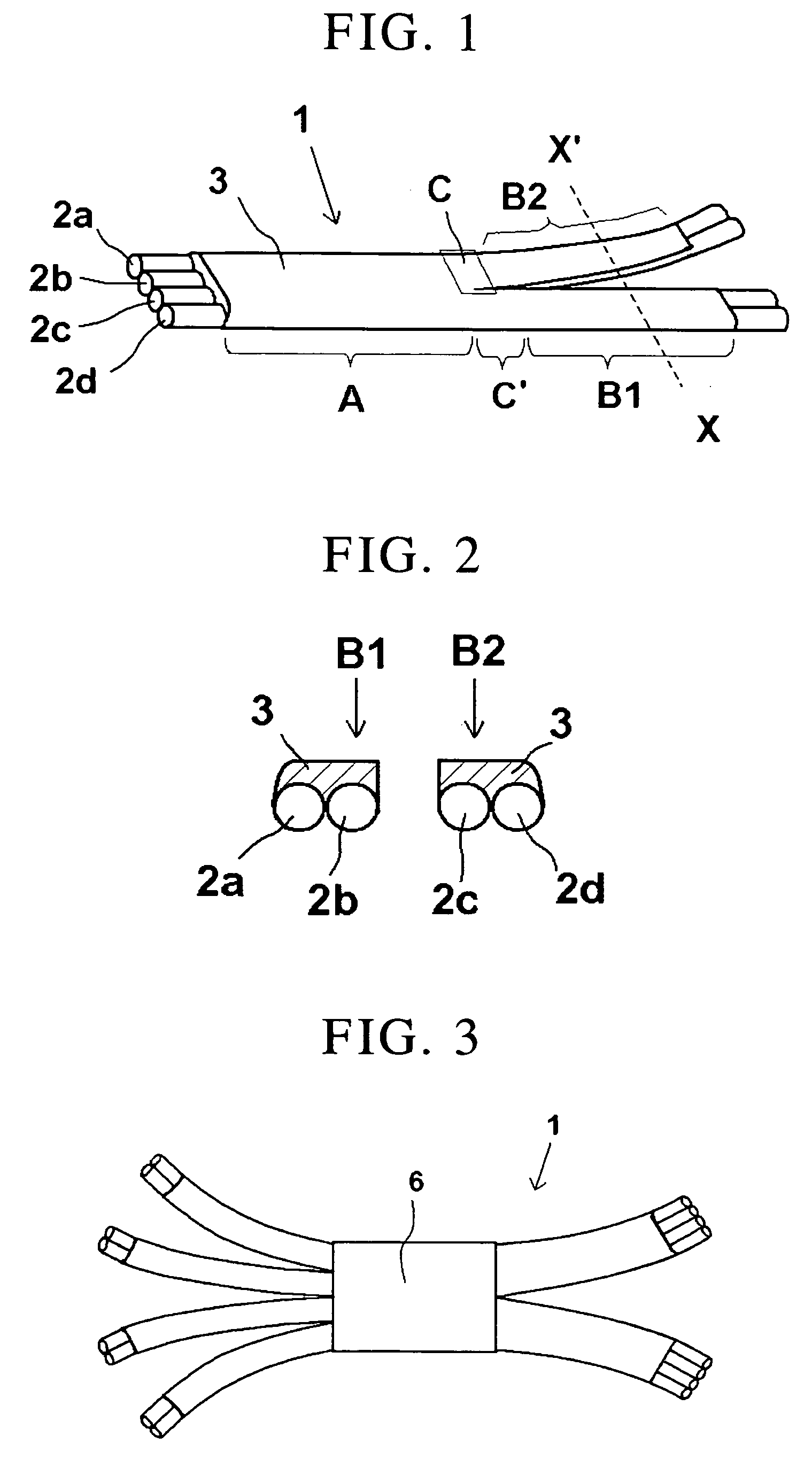
[0102]Eight 30-cm long coated optical fibers were aligned, and a covering material was applied to the coated optical fibers using the application apparatus in the same manner as in Example 1. The obtained assembly was held still for one hour in room temperature to cure the covering material to obtain a covering layer. Next, a 2-cm strip at the center of the optical fiber wiring sheet was covered with UV setting resin to a thickness of 2 mm, after which the UV setting resin was irradiated by a UV lamp for 2 minutes at an irradiation intensity of 20 mW / cm2 to cure the resin. Thereafter, the optical fibers were separated from the substrate, a covering material was formed, and then the covering material was completely cured in room temperature. Furthermore, clear resin was applied to the center part as a protective member (6) to form a covering layer, as shown in FIG. 3. Thereafter, the ends of four bundles each consisting of two coated optical fibers were held separately on one end of ...
example 3
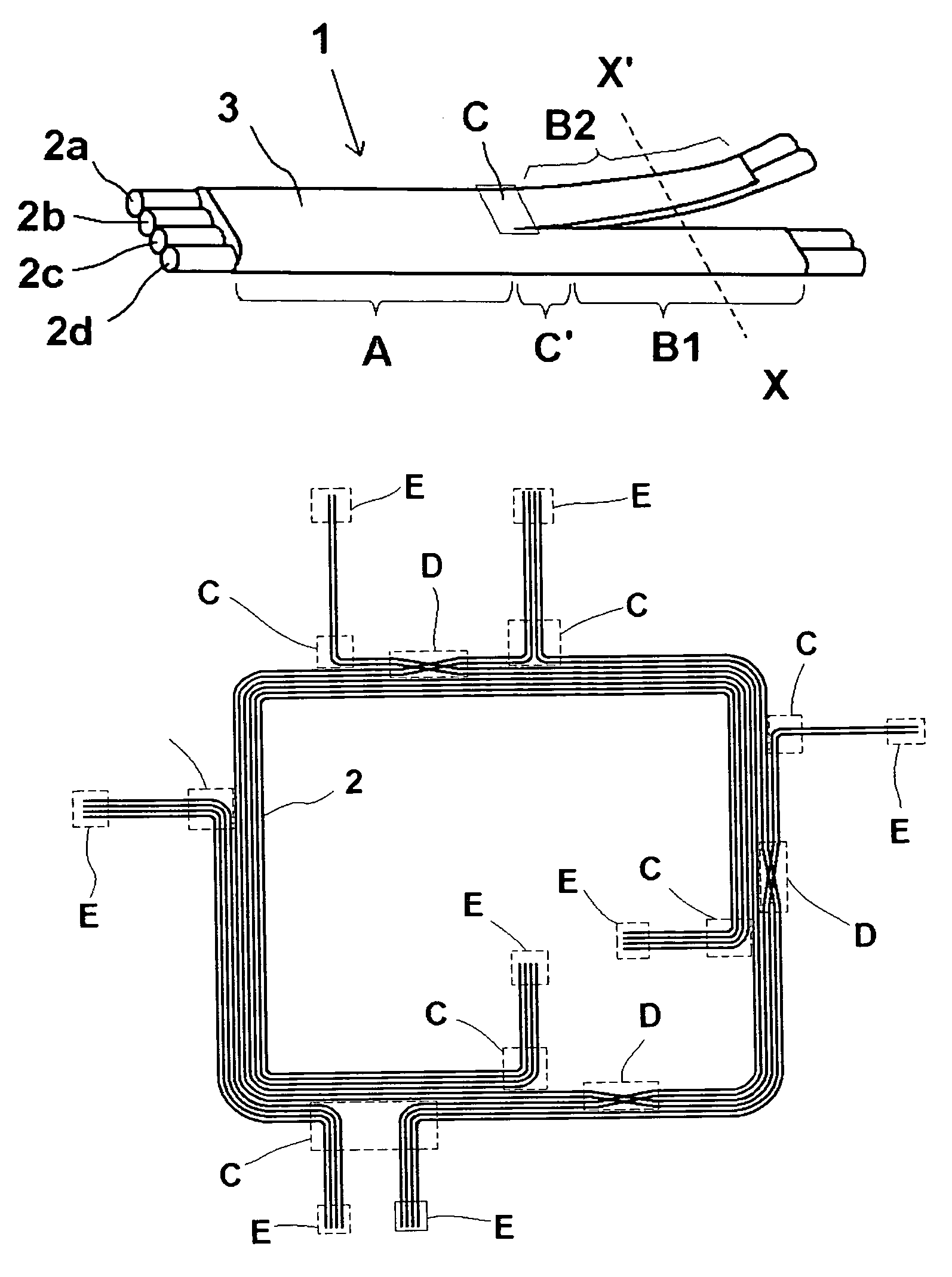
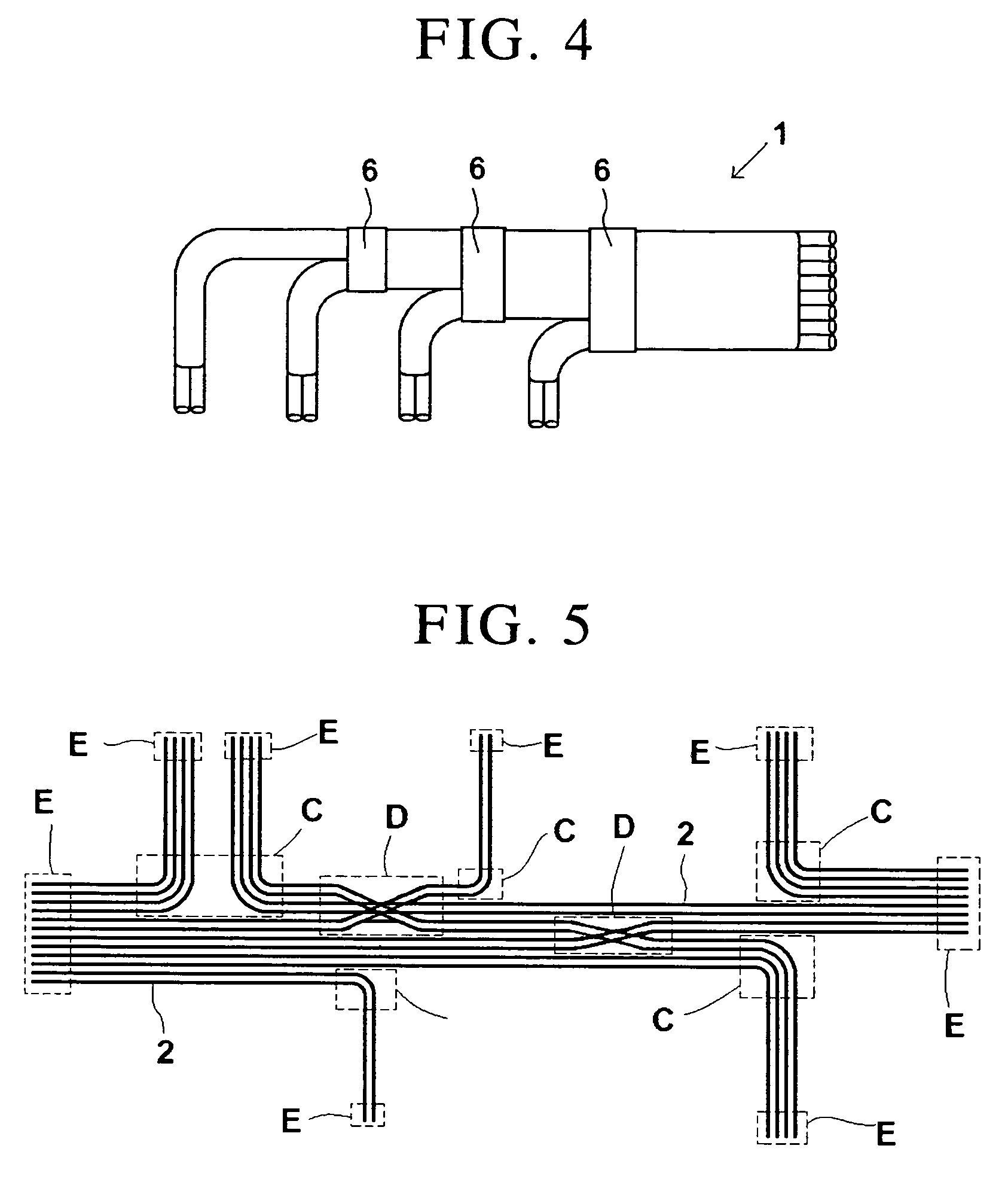
[0103]Eight 50-cm long coated optical fibers were aligned, and a covering material was applied to the entire coated optical fibers in the same manner as in Example 1 to form a covering layer. Next, a heat-shrinkable tube with slit (length: 2 cm) was placed, as a protective member (6), at the branching position of the coated optical fibers, and then the tube was shrunk using a heater. Thereafter, the coated optical fibers were branched into four bundles of two coated optical fibers each at intervals of 5 cm. This produced a fan-out optical fiber wiring sheet with its eight cores branching in sets of two cores at constant intervals, as shown in FIG. 4.
PUM
 Abstract
Description
Claims
Application Information
 - Generate Ideas
- Intellectual Property
- Life Sciences
- Materials
- Tech Scout
- Unparalleled Data Quality
- Higher Quality Content
- 60% Fewer Hallucinations
Browse by: Latest US Patents, China's latest patents, Technical Efficacy Thesaurus, Application Domain, Technology Topic, Popular Technical Reports.
© 2025 PatSnap. All rights reserved.Legal|Privacy policy|Modern Slavery Act Transparency Statement|Sitemap|About US| Contact US: help@patsnap.com


