
Ink jet UV curing

a technology of ink jets and ultraviolet light, applied in drying, lighting and heating apparatus, furniture, etc., can solve the problems of running, bleeding, or smudging of ink, and achieve the effect of convenient use and efficien

Inactive Publication Date: 2006-11-21
CON TROL CURE
View PDF62 Cites 81 Cited by
  • Summary
  • Abstract
  • Description
  • Claims
  • Application Information

AI Technical Summary

Benefits of technology

This method prevents ink dots from growing, expanding, running, bleeding, or smudging by ensuring rapid partial curing and complete polymerization, enhancing printing efficiency and quality.

Problems solved by technology

Also, oftentimes the ink dots are applied so rapidly that some running, bleeding and / or smudging of ink occurs.

Method used


Image

  • Ink jet UV curing
  • Ink jet UV curing
  • Ink jet UV curing

Examples


Embodiment Construction

[0049]A detailed description of the preferred embodiments and best modes for practicing the invention are described herein.

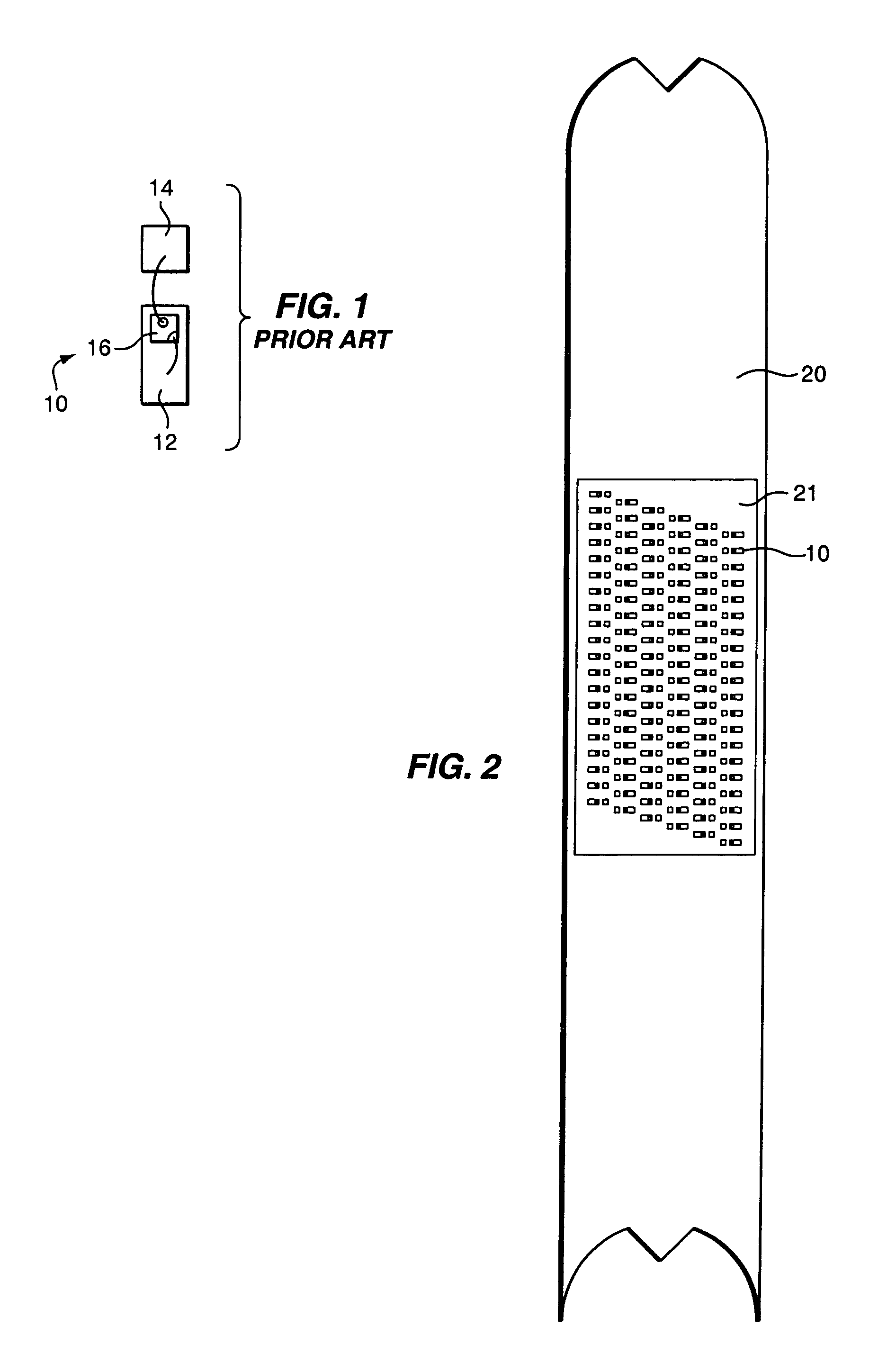
[0050]Referring now to the drawings in greater detail, there is illustrated in FIG. 1 a prior art ultraviolet light-emitting diode (UV LED) assembly 10 including a cathode pad 12 and an anode 14 mounting a chip 16, which comprises a UV LED chip 16. Each cathode pad 12 (FIG. 1) is connected to a wire conductor, as is each anode 14.

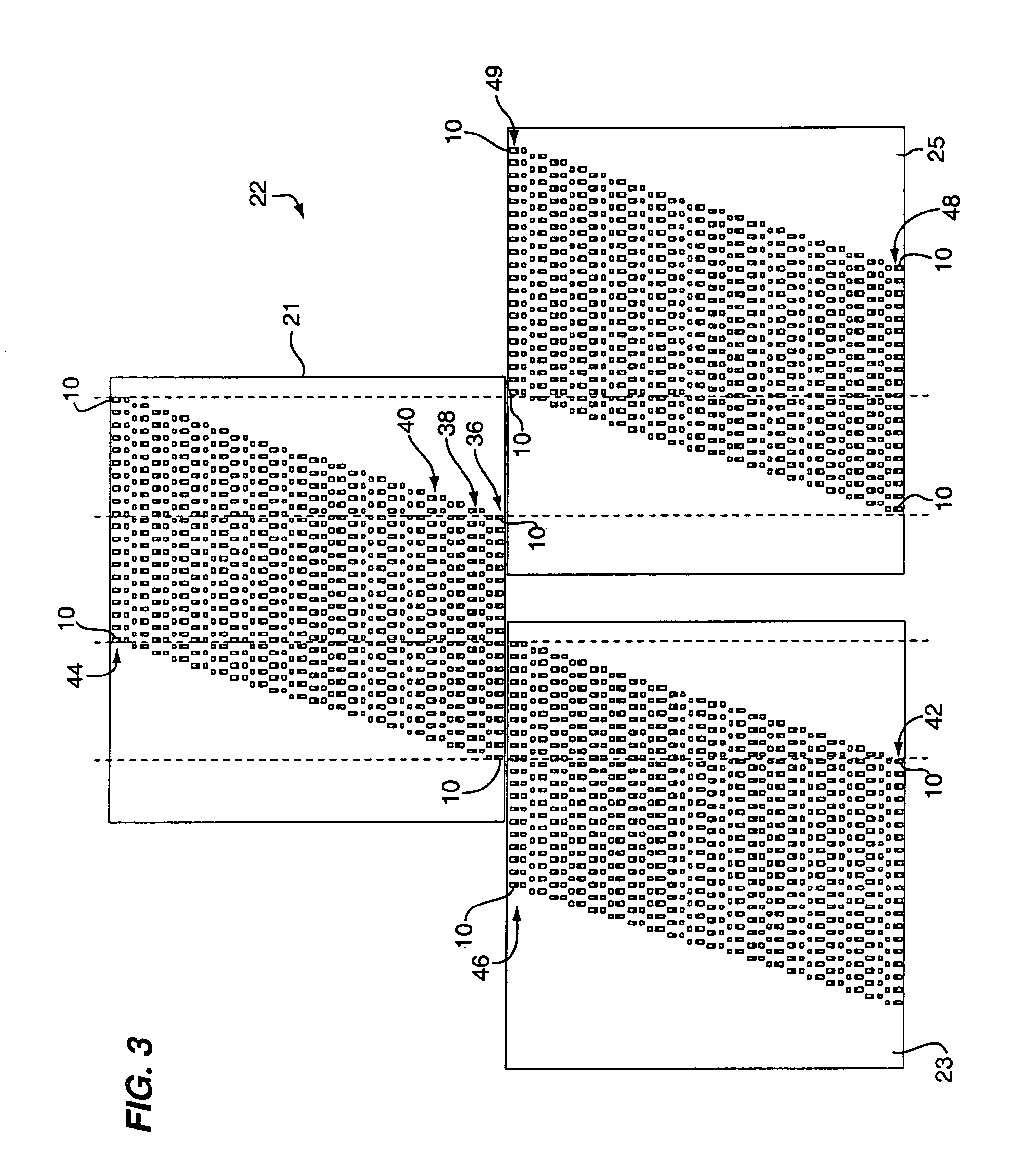
[0051]Referring now to FIG. 2, there is illustrated therein a primary light source comprising a building block 20 having a first array 21 of the UV LED assemblies 10 thereon, namely, pads 12 and anodes 14, which provide a plurality of UV LED chips 16. The building blocks are designed to mate with similar building blocks to form a group 22 of arrays 21, 23 and 25 as shown in FIGS. 3 and 4. In this way, several of the blocks 20 can matingly engage each other and be arranged in a pattern (e.g., like tiles on a floor) on a panel 28 (FIG. 4)...


PUM

PropertyMeasurementUnit
wavelengthsaaaaaaaaaa

Abstract

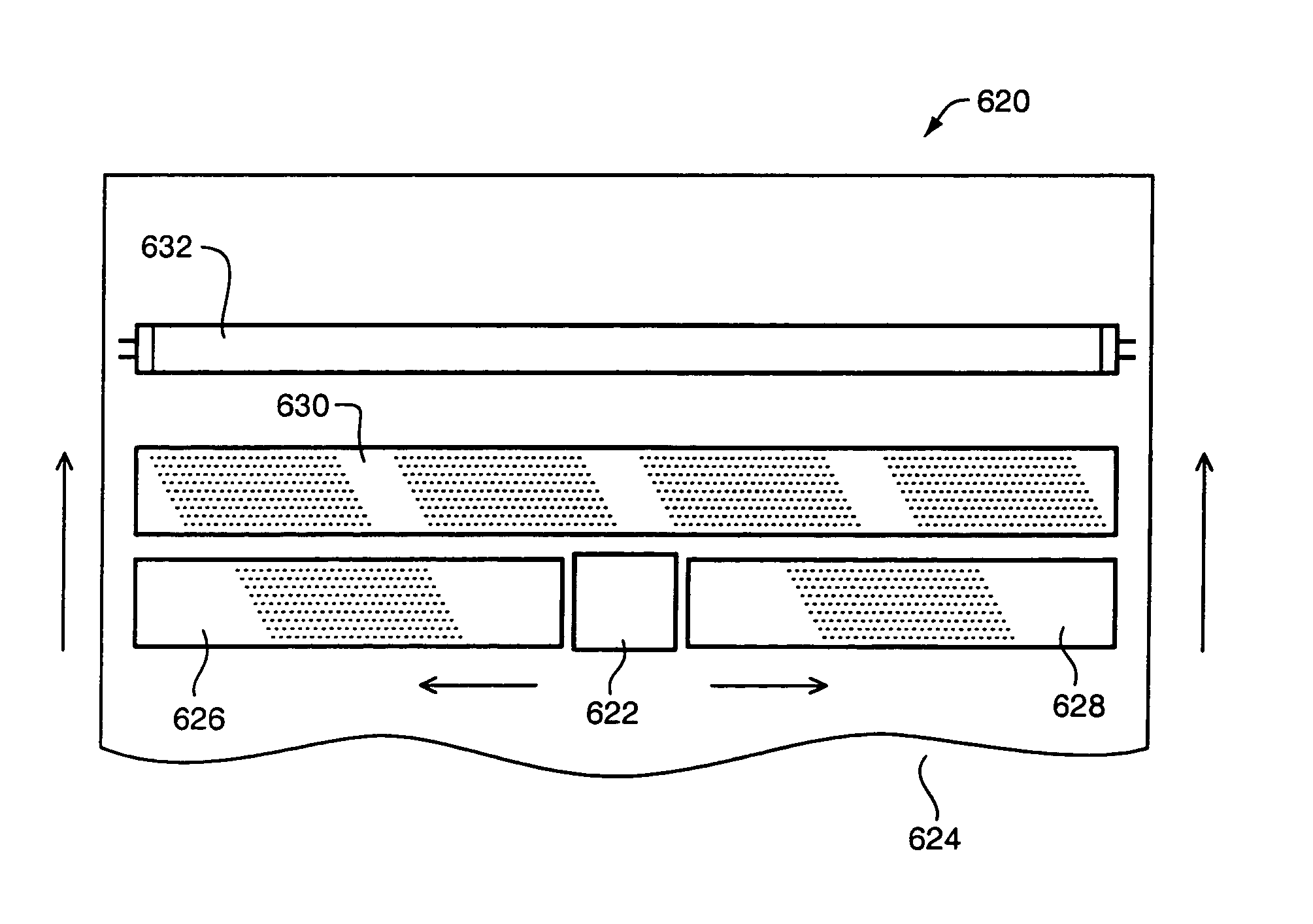
A method and apparatus for printing a product, article or other object at a printing station and for enhancing the application of UV light to UV photo initiators in a UV curable ink being applied to a product, article or other object at the printing station, comprising the steps for: printing a UV-curable ink with a printing head of a printer on a substrate, product, article or other object at a printing station; providing a primary light source of UV light preferably comprising at least one set of UV-LED arrays of UV-LED chips adjacent the printing head; and partially curing the ink dots by emitting light on the ink dots from the primary light source to set and partially polymerize, coalesce, coagulate and / or gel the ink dots so as to substantially inhibit the growth of the ink dots and prevent, running or smudging of the ink dots. The curing of the ink dots are completed by emitting light on the ink dots from a secondary light source, such as from one or more fluorescent lamps.

Description

CROSS REFERENCE TO RELATED APPLICATIONS[0001]This application is a continuation-in-part of U.S. application Ser. No. 10 / 789,020 filed Feb. 20, 2004 for UV Curing for Ink Jet Printer which is a continuation-in-part of U.S. application Ser. No. 10 / 753,947 filed Jan. 7, 2004 for a UV Curing Method and Apparatus, a continuation-in-part of U.S. application Ser. No. 10 / 386,980 filed Mar. 12, 2003 for Multiple Wavelength UV Curing and a continuation-in-part of U.S. application Ser. No. 10 / 339,264 filed Jan. 9, 2003 for a Light Emitting Apparatus and Method for Curing Inks, Coatings and Adhesives.BACKGROUND OF THE INVENTION[0002]1. Field of the Invention[0003]The present invention relates to a method and apparatus for utilizing ultraviolet (UV) light and other light sources for curing ink on products, articles or other objects as the ink is applied to the products, articles or other objects.[0004]2. Description of the Related Art[0005]Heretofore, UV-light emitting diode (LED) arrays have be...

Claims


Application Information

Patent Timeline
Patent Type & Authority Patents(United States)
IPC IPC(8): B05D3/06B41F23/04B41J3/407B41J11/00F26B3/28
CPCB41F23/0409B41J3/4071B41J11/002F26B3/28B29C2035/0827B41J11/00214B41J11/00218
Inventor SIEGEL, STEPHEN B.
Owner CON TROL CURE
Learn More