Radio terminal, radio base station, and radio communication system
a radio communication system and radio terminal technology, applied in power management, instruments, high-level techniques, etc., can solve the problems of consuming more power and the radio terminal cannot switch from the wake-up state to the sleep state, and achieve the effect of preventing the radio terminal from running down
- Summary
- Abstract
- Description
- Claims
- Application Information
AI Technical Summary
Benefits of technology
Problems solved by technology
Method used
Image
Examples
first embodiment
Configuration of Radio Communication System
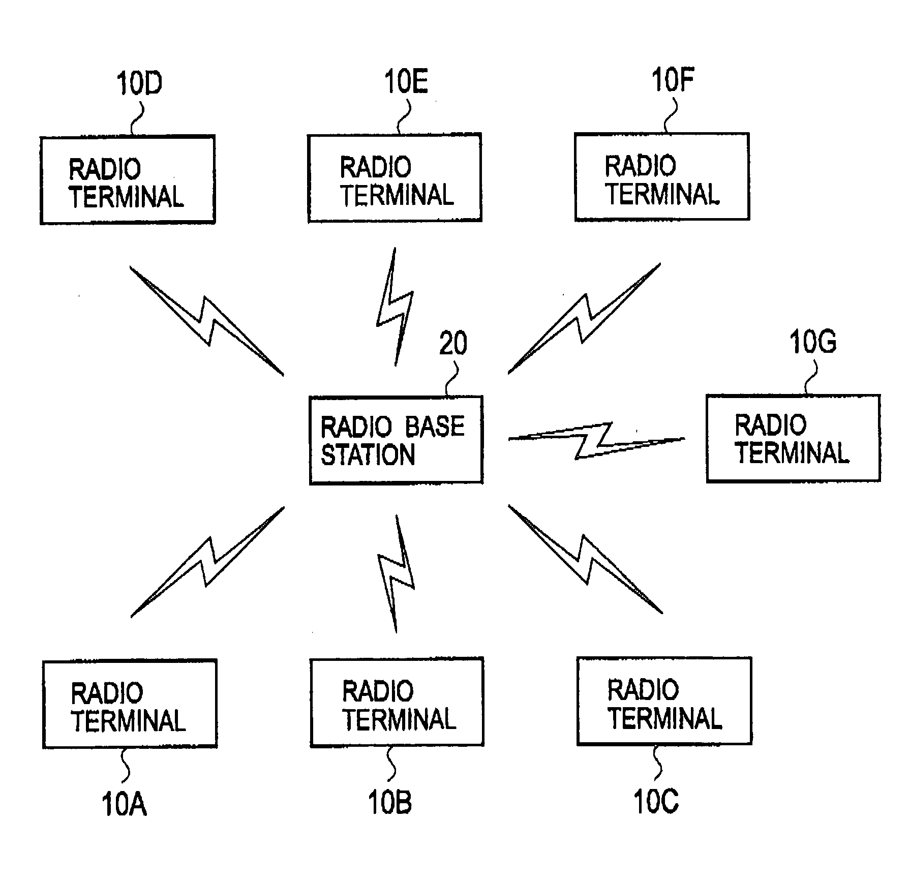
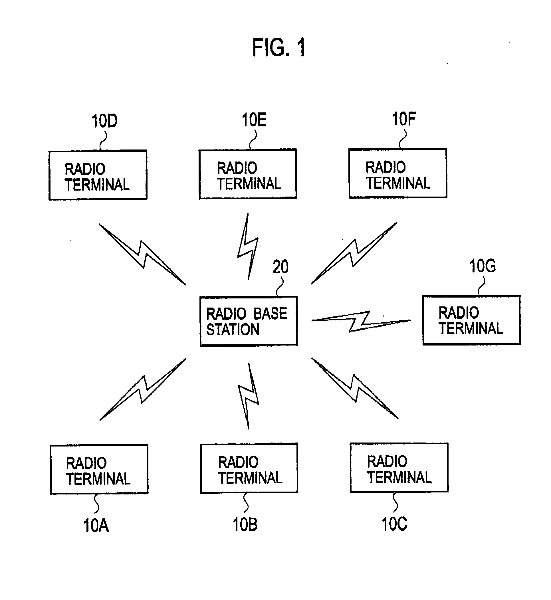
[0049]With reference to the drawing, a description will be given below of the configuration of a radio communication system according to a first embodiment. FIG. 1 is a diagram illustrating the radio communication system according to the first embodiment.
[0050]As illustrated in FIG. 1, the radio communication system includes a plurality of radio terminals 10 (radio terminals 10A to 10G) and a radio base station 20. In the radio communication system, radio communication is performed using a predetermined radio band. Of course, there can be any number of the radio terminals 10.
[0051]The radio communication system is, for example, a wireless LAN communication system or the like. The radio communication system employs a radio communication scheme using, for example, carrier sense multiple access with collision avoidance (CSMA / CA).
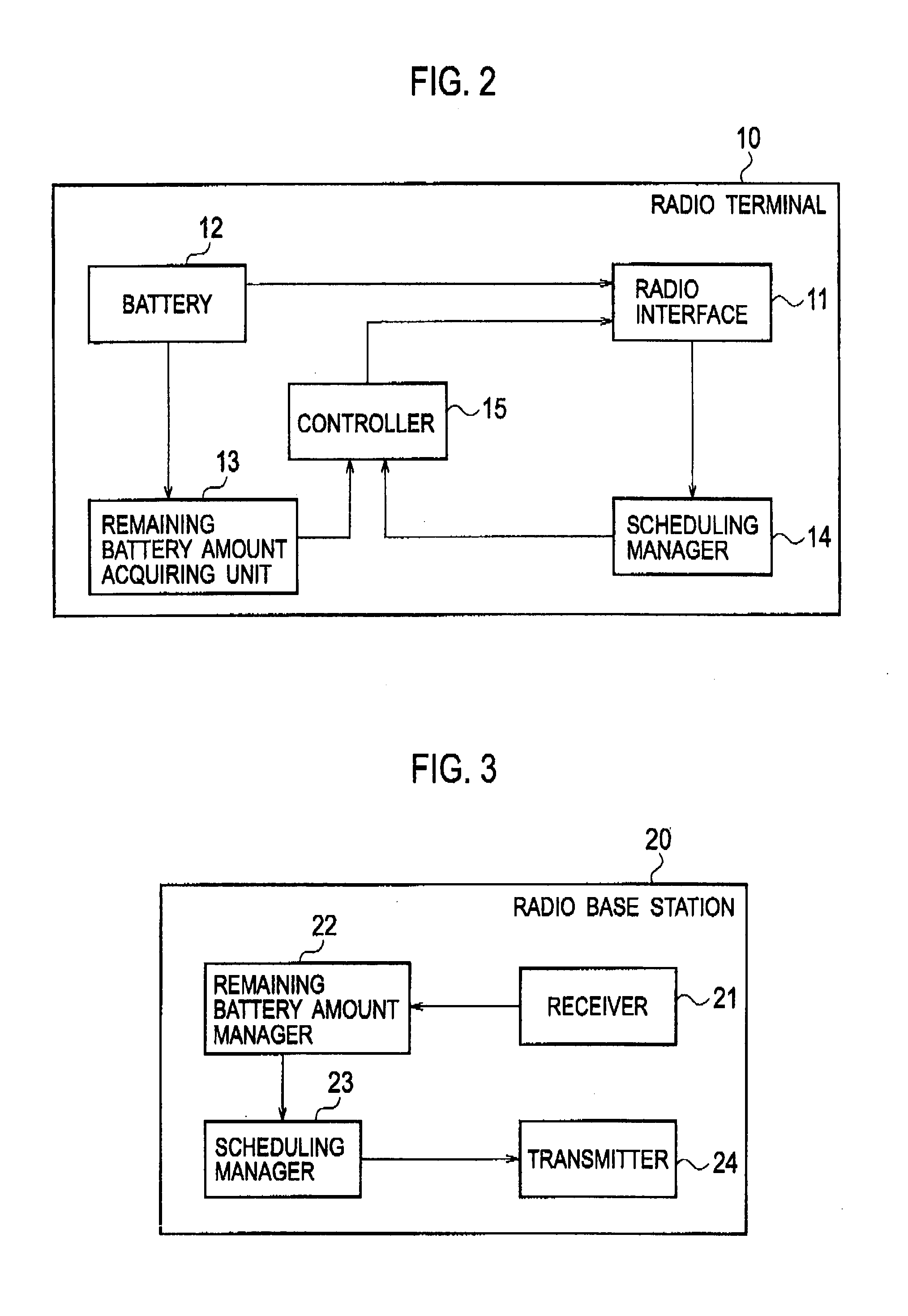
[0052]The radio terminal 10 is a terminal constituting of a CPU, a ROM, a RAM, and others. The radio terminal 10 is ...
second embodiment
[0087]With reference to the drawings, a description will be given below as to a second embodiment. The following mainly describes differences between the first embodiment and the second embodiment.
[0088]Specifically, the radio base station 20 performs the communication order scheduling in the first embodiment. In contrast, a representative radio terminal being one of the plurality of radio terminals 10 performs the communication order scheduling in the second embodiment.
[0089]It should be noted that the radio terminals 10 other than the representative radio terminal have the same configuration as that described in the first embodiment, except that each of the radio terminals 10 other than the representative radio terminal transmits the remaining battery amount data to the representative radio terminal.
[0090]Each of the radio terminals 10 other than the representative radio terminal may transmit remaining battery amount data directly to the representative radio terminal. Alternativel...
third embodiment
[0106]With reference to the drawings, a description will be given below as to a third embodiment. The following mainly describes differences between the first embodiment and the third embodiment.
[0107]Specifically, the radio base station 20 performs the communication order scheduling in the first embodiment. In contrast, each of the radio terminals 10 performs the communication order scheduling in an autonomous distributed manner in the third embodiment.
[0108]Each of the radio terminals 10 broadcasts an order of its own terminal for performing communication (hereinafter called an own-terminal communication order), instead of the remaining battery amount data. Accordingly, each of the radio terminals 10 receives an order of each of the other different radio terminals where they perform communication (different-terminal communication order). The own-terminal communication order and the different-terminal communication order are set based on the battery levels of the radio terminals 10...
PUM
 Abstract
Description
Claims
Application Information
 - R&D
- Intellectual Property
- Life Sciences
- Materials
- Tech Scout
- Unparalleled Data Quality
- Higher Quality Content
- 60% Fewer Hallucinations
Browse by: Latest US Patents, China's latest patents, Technical Efficacy Thesaurus, Application Domain, Technology Topic, Popular Technical Reports.
© 2025 PatSnap. All rights reserved.Legal|Privacy policy|Modern Slavery Act Transparency Statement|Sitemap|About US| Contact US: help@patsnap.com


