
Method and apparatus for satellite positioning

a satellite positioning and apparatus technology, applied in the field of satellite positioning apparatus, can solve the problems of deterioration of the positioning stability of the satellite positioning apparatus, user questioning the performance of the gps system, and large shifts in determined positions, so as to suppress the large shift in determined positions, suppress the effect of large positional shift and good correction of determined positions

Inactive Publication Date: 2006-11-14
ALPINE ELECTRONICS INC
View PDF11 Cites 11 Cited by
  • Summary
  • Abstract
  • Description
  • Claims
  • Application Information

AI Technical Summary

Benefits of technology

"The present invention relates to a satellite positioning apparatus and a navigation apparatus that can suppress shifts in position determined by satellite positioning. The apparatus includes a satellite position-determining unit, a determined position output unit, and a velocity vector calculating unit. The apparatus can output the determined position based on the signals received from the satellites and the velocity vector calculated by the velocity vector calculating unit, instead of the position determined by the satellite position-determining unit, when certain conditions are met. The navigation apparatus can also use map matching to correct the determined position and suppress rapid changes in position. These technical effects can improve the accuracy and reliability of satellite positioning and navigation."

Problems solved by technology

Accordingly, a change in the combination of satellites used in position determination may cause a deterioration in positioning stability of a satellite positioning apparatus, so that large shifts in determined positions may occur.
The occurrence of the large shifts in determined positions may cause a user to question the performance of the GPS system.
Additionally, it is difficult to correct the position determined by the satellite positioning apparatus by using techniques such as map matching, which perform correction by collating the determined position with previously determined positions, loci represented by the positions' records, and a road map.

Method used


Image

  • Method and apparatus for satellite positioning
  • Method and apparatus for satellite positioning
  • Method and apparatus for satellite positioning

Examples


Embodiment Construction

[0027]An embodiment of the present invention is described below by exemplifying an application of the present invention to a navigation system provided in an automobile.

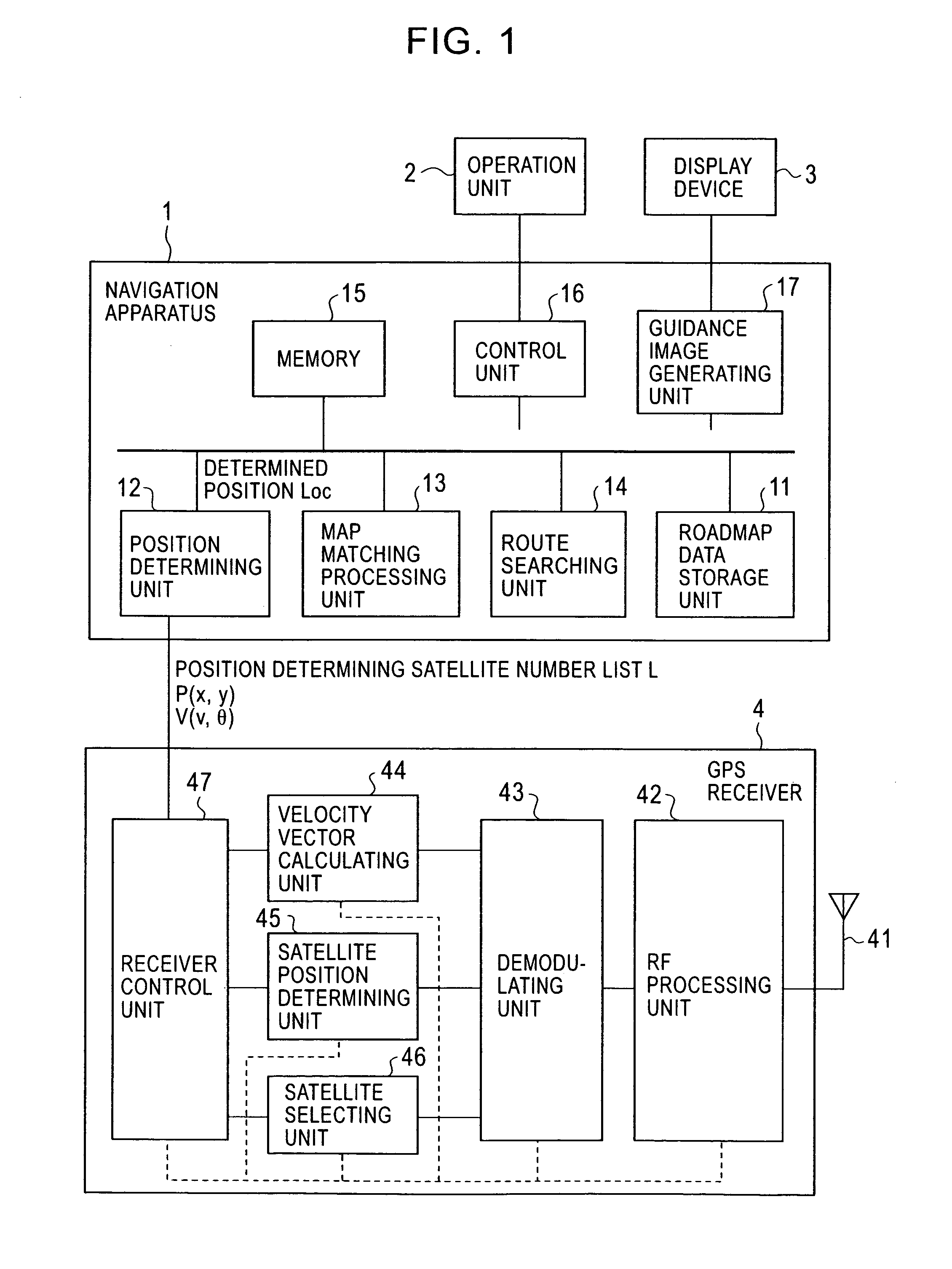
[0028]As shown in FIG. 1, the navigation system includes a navigation apparatus 1, an operation unit 2, a display device 3, and a GPS receiver 4. The navigation apparatus 1 includes a roadmap data storage unit 11 that is a storage unit (such as a digital versatile disk drive or a hard disk drive) storing roadmap data, a position determining unit 12, a map matching processing unit 13, a route searching unit 14, a memory 15, a control unit 16, and a guidance image generating unit 17.

[0029]The GPS receiver 4 includes an antenna 41, a RF processing unit 42, a demodulating unit 43, a velocity vector calculating unit 44, a satellite position determining unit 45, a satellite selecting unit 46, and a receiver control unit 47. The RF processing unit 42 performs processing such as amplifying signals received by the antenna 41,...


PUM


Abstract

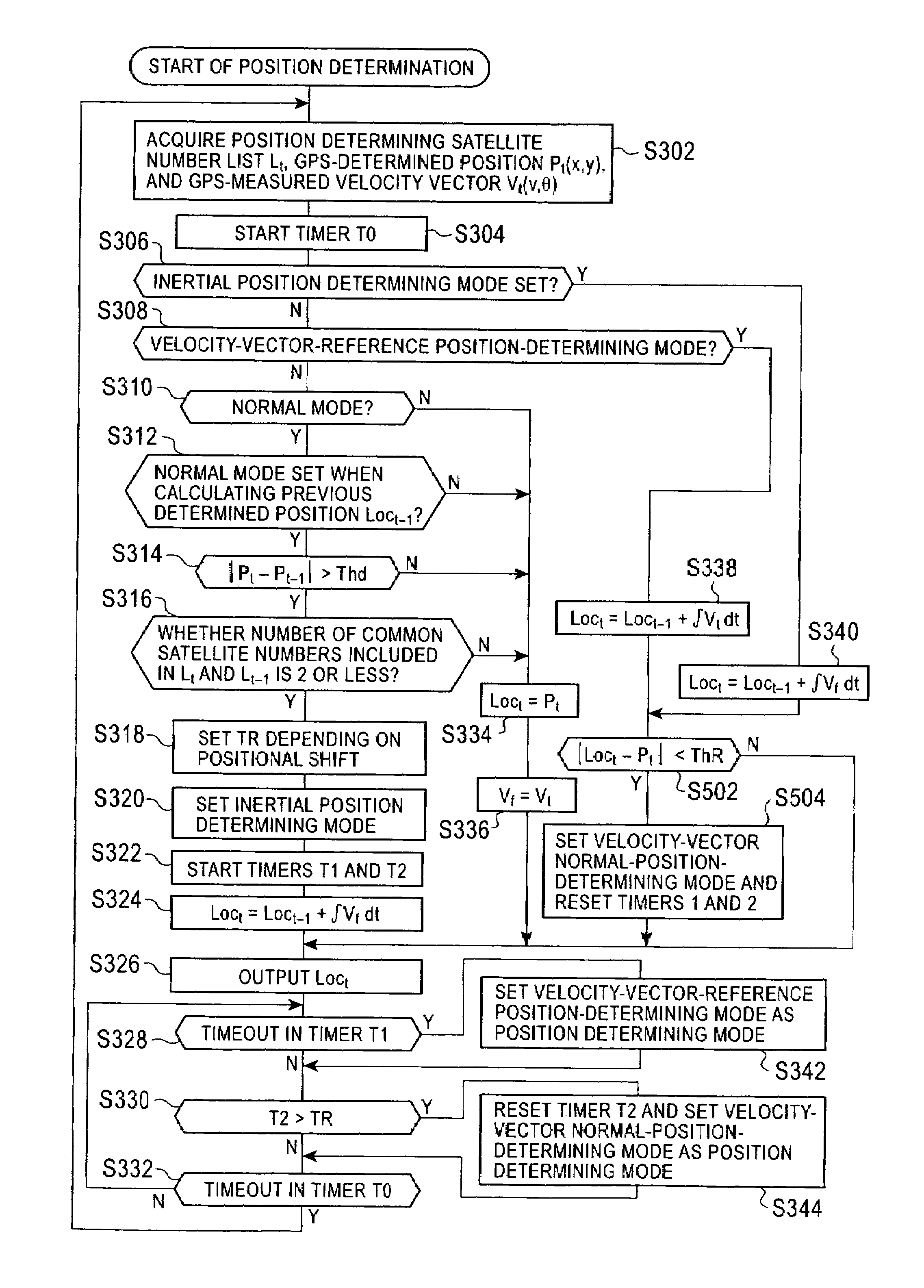
When there is a large difference greater than a threshold value between a position determined at a time in satellite positioning by a GPS receiver based on a propagation delay of signals received from a GPS satellite, and an anterior position determined at an anterior time in satellite positioning by the GPS receiver, in position determination in a first period after the times, a present position is found based on a velocity vector found at the anterior time by the GPS receiver based on a Doppler shift occurring in the signals received from the GPS satellite and a previously determined position. In position determination in a second period after the first period, the present position is found based on a velocity vector found in the second period and the previously determined position. After that, processing is returned in which a satellite-determined position is used as a determined position.

Description

BACKGROUND OF THE INVENTION[0001]1. Field of the Invention[0002]The present invention relates to a satellite positioning apparatus, in a satellite positioning system such as the Global Positioning System (GPS), for determining the position of the satellite positioning apparatus based on signals received from satellites.[0003]2. Description of the Related Art[0004]GPS is a widely used satellite navigation system that includes a plurality of satellites and a satellite positioning apparatus that moves with a mobile object such as an automobile.[0005]Positioning technology for GPS receivers select from satellites with receivable signals, a combination of satellites in which the optimal dilution of precision (DOP) may be determined depending on the geometric constellation of the satellites. A position by using signals received from the satellites may also be determined (e.g., Japanese Unexamined Patent Application Publication No. 5-297104).[0006]Additionally, position determination and p...

Claims


Application Information

Patent Timeline
Patent Type & Authority Patents(United States)
IPC IPC(8): G01S1/02G09B29/00G01C21/00G01C21/26G01S19/28G01S19/42G01S19/50G08G1/0969G09B29/10
CPCG01C21/26G01S19/28G01S19/42G01S19/50
Inventor WAKAMATSU, KOTARO
Owner ALPINE ELECTRONICS INC
Learn More