Method for controlling of thermal donor formation in high resistivity CZ silicon
a technology of thermal donor and silicon, which is applied in the field of silicon wafers and semiconductor material substrates, can solve the problems of contaminated molten silicon with various impurities, harmful or beneficial precipitates, and device operation, and achieve high resistivity surface layers, high resistivity, and high oxygen density
- Summary
- Abstract
- Description
- Claims
- Application Information
AI Technical Summary
Problems solved by technology
Method used
Image
Examples
example 1
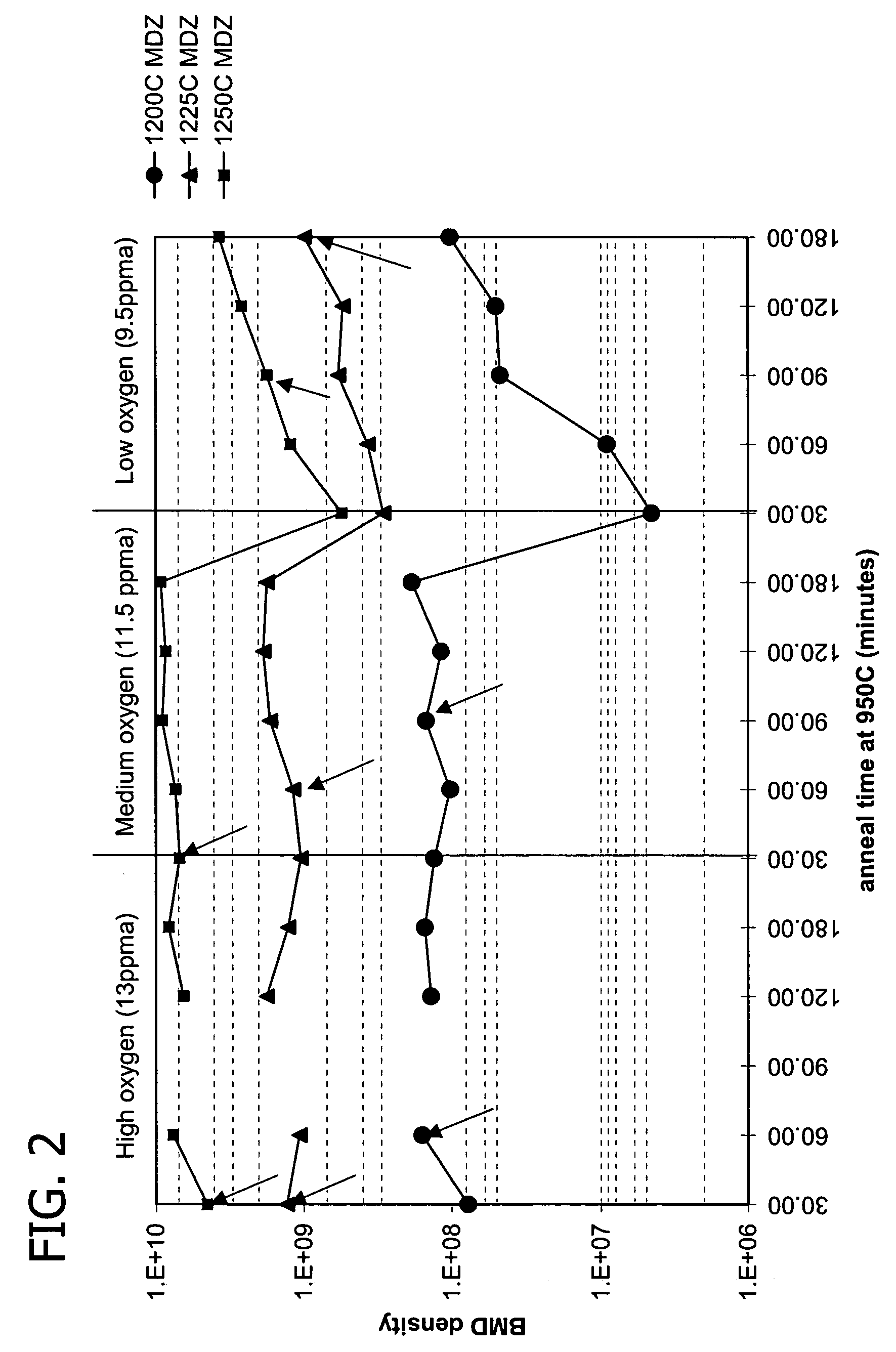
[0073]Example 1 and FIG. 2 demonstrate the gettering capability of ideal precipitating wafers over a range of oxygen concentration. In the first set of experiments, ideal precipitating wafers with an oxygen concentration of 13 ppma were produced at a step S1 heat treatment temperature of 1200° C., followed by oxygen bulk precipitate growth at 950° C. over a range of 30 minutes to 180 minutes. The evaluations were repeated for 1225° C. and 1250° C. step S1 heat treatment temperatures. In a second and third set of experiments, the first set of experiments were repeated for ideal precipitating wafers with oxygen concentrations of 11.5 ppma and 9.5 ppma respectively. Gettering capability was measured by contaminating the wafer back surface with nickel. The arrows in FIG. 2 indicate the onset of complete gettering. The data show that bulk precipitate density above the threshold for effective gettering may be obtained for ideal precipitating wafers over a range of oxygen concentration, an...
example 2
[0074]Four wafers were cut from two sections of a high resistivity CZ crystal. Three wafers were given ideal precipitating wafer heat-treatments at 1235° C., 1250° C. and 1275° C., respectively. The fourth wafer was a control that was not given an ideal precipitating wafer heat-treatment. Each wafer was then quartered and given the following secondary anneals:
[0075]
Wafer GG,4 hours at 800° C. followed by 16 hours atQuarter 1 (GGQ1):1000° C.;Wafer GG,8 hours at 800° C. followed by 16 hours atQuarter 2 (GGQ2):1000° C.;Wafer GG,ramp from 800° C. to 1000° C. at 1° C. / minQuarter 3 (GGQ3):followed by 1 hour at 1000° C.; andWafer GG,ramp from 800° C. to 1000° C. at 2° C. / minQuarter 4 (GGQ4):followed by 1 hour at 1000° C.
[0076]Following the secondary anneals, the BMD density was measured by OPP (Optical Precipitate Profiler). The OPP method is an applied method of Normalski type differential interference microscope. In the method, laser beam from light source is separated to two orthogonal ...
example 3
[0079]The radial initial and final oxygen concentration (Oi) of the annealed GG wafers from Example 2, a second set of wafers (GA) prepared as in example 2, and corresponding untreated GG and GA wafers was determined. The results, reported in Oi (ppma) at radial distances from the wafer (mm) for the annealed wafers with the indicated ideal precipitating wafer treatment temperature in parentheses, are given in the table below.
[0080]
Wafer10 mm30 mm50 mm70 mm90 mmGG initial12.212.112.011.911.5GA initial11.211.010.910.910.5GGQ1 (1235)9.08.68.78.99.0GGQ2 (1235)7.97.57.67.88.1GGQ3 (1235)12.012.011.911.711.5GGQ4 (1235)12.612.012.011.911.6GAQ1 (1235)9.59.09.19.19.2GAQ2 (1235)8.38.08.28.38.6GAQ3 (1235)11.111.010.810.810.4GAQ4 (1235)11.111.010.810.810.5GGQ1 (1250)7.67.47.47.68.0GGQ2 (1250)6.15.95.96.06.5GGQ3 (1250)12.212.012.011.911.5GGQ4 (1250)12.212.112.112.011.5GAQ1 (1250)8.58.28.38.48.6GAQ2 (1250)6.96.66.66.87.3GAQ3 (1250)11.010.910.910.810.5GAQ4 (1250)11.110.911.010.910.5GGQ1 (1275)5.75....
PUM
| Property | Measurement | Unit |
|---|---|---|
| resistivities | aaaaa | aaaaa |
| resistivity | aaaaa | aaaaa |
| temperature | aaaaa | aaaaa |
Abstract
Description
Claims
Application Information
 - R&D
- Intellectual Property
- Life Sciences
- Materials
- Tech Scout
- Unparalleled Data Quality
- Higher Quality Content
- 60% Fewer Hallucinations
Browse by: Latest US Patents, China's latest patents, Technical Efficacy Thesaurus, Application Domain, Technology Topic, Popular Technical Reports.
© 2025 PatSnap. All rights reserved.Legal|Privacy policy|Modern Slavery Act Transparency Statement|Sitemap|About US| Contact US: help@patsnap.com


