Failure control unit

Inactive Publication Date: 2006-11-07
FUJITSU LTD
View PDF7 Cites 43 Cited by
  • Summary
  • Abstract
  • Description
  • Claims
  • Application Information

AI Technical Summary

Benefits of technology

[0011]In view of the foregoing, it is an object of the present invention to provide a transmission unit which performs failure recovery processing efficiently using limited network resources.
[0012]It is another object of the present invention to provide a failure recovery method which enables a network to recover from failure, efficiently using limited resources.

Problems solved by technology

The above-described conventional failure recovery technique, however, requires a lot of network resources to be allocated previously for protection purposes.
This is very inefficient in terms of resource usage.
While it surely contributes to the improved availability of networks, the conventional protection method causes a problem in operability and usability of communication services.

Method used


Image

  • Failure control unit
  • Failure control unit
  • Failure control unit

Examples


first embodiment

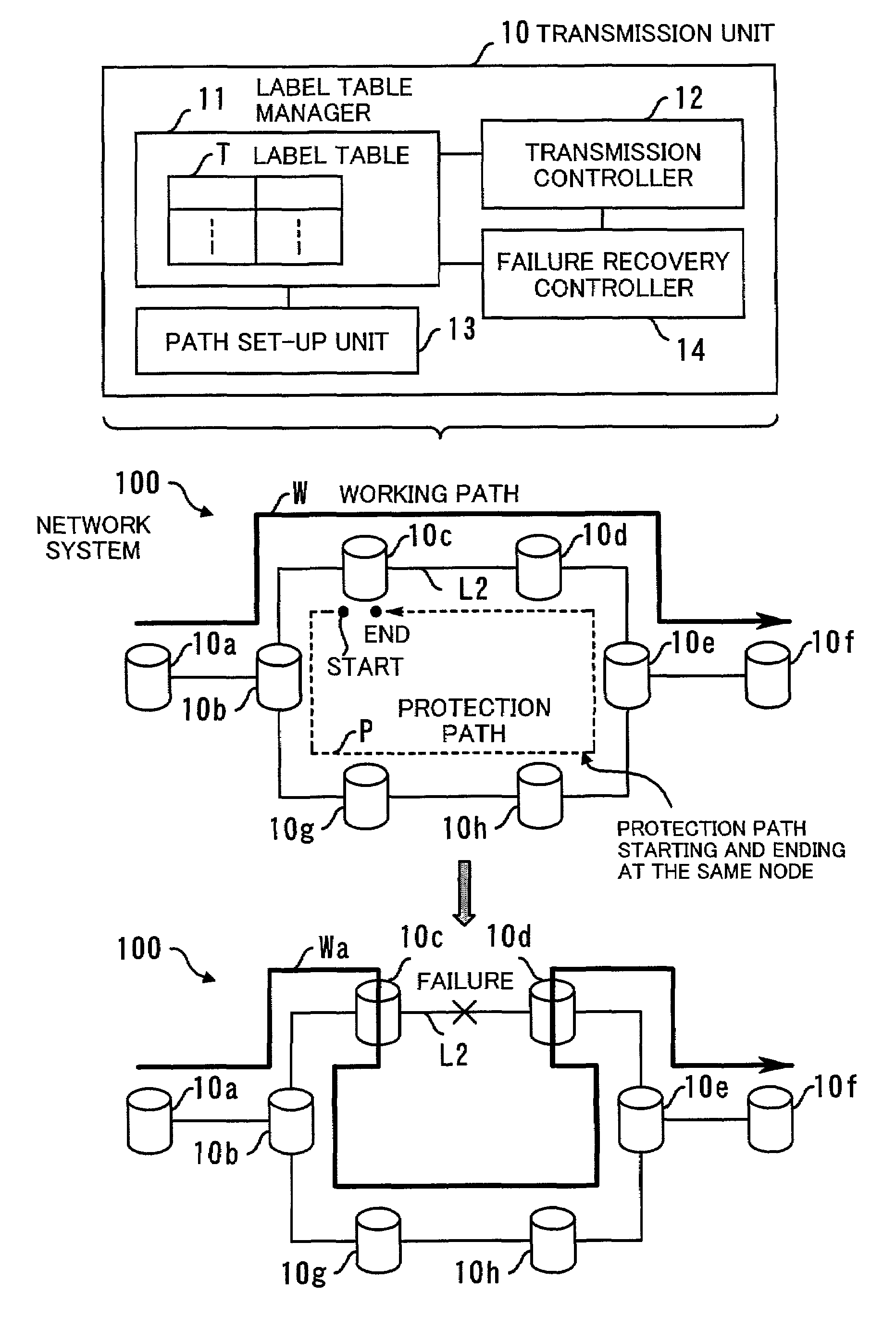
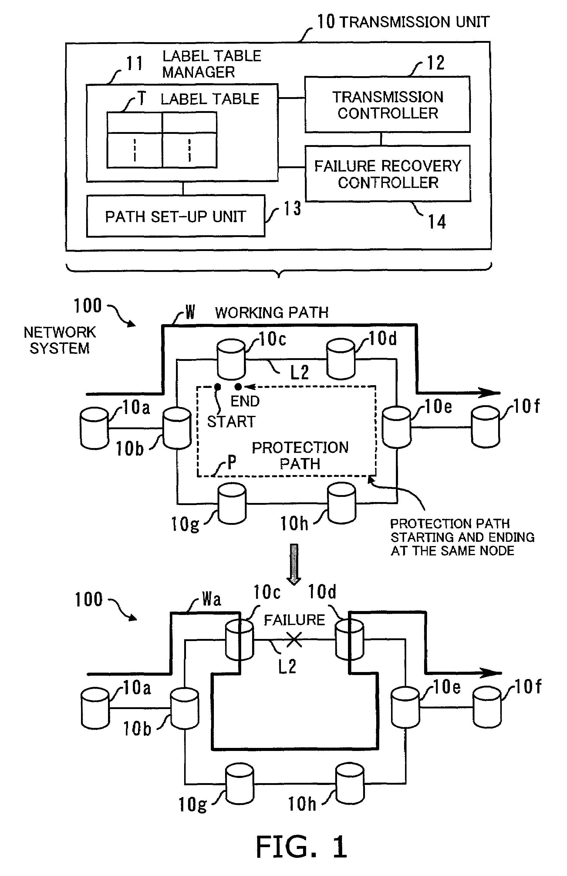
[0031]FIG. 1 is a conceptual view of a transmission unit according to the present invention. The transmission unit 10 is a piece of signal transmission equipment for use in a label-switched network, with the capability of recovering from a link failure. The proposed transmission unit 10 can be applied to packet networks, connection-oriented optical networks such as SONET and SDH, and other communication environments. This description will first discuss MPLS packet routing systems with reference to FIGS. 1 to 20, and then an optical network application with reference to FIG. 21.

[0032]Referring first to the upper half of FIG. 1, the transmission unit 10 comprises the following elements: a label table manager 11, a transmission controller 12, a path set-up unit 13, and a failure recovery controller 14. The transmission unit 10 delivers individual short information messages called packets, using label-switching techniques. Each labeled packet is forwarded from one transmission unit to t...

third embodiment

[0103]While the network system of FIGS. 12 and 13 offers as many protection paths as the number of working paths, it is also possible to reduce the number of protection paths if necessary. In this case, the working paths may be prioritized as in the way explained in FIG. 11.

[0104]Referring next to FIGS. 14 to 17, a fourth embodiment of the present invention will be described. The foregoing three embodiments reconfigure the network to loop back incoming packets at particular LSRs located near the failed link. Those loopback point LSRs, however, would have to perform unnecessary packet routing, consuming extra link resources. To address this issue, the fourth embodiment incorporates a mechanism to eliminate loopback points, if any, when switching a working path W to a protection path P.

fourth embodiment

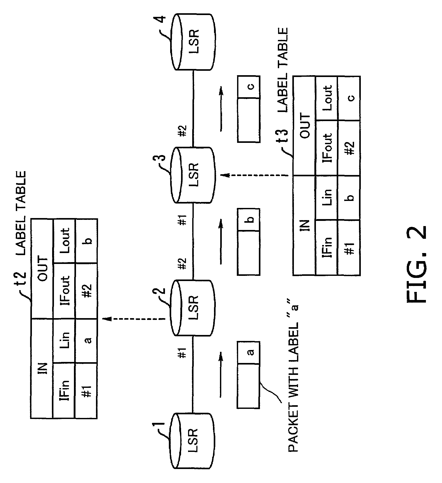
[0105]FIGS. 14 to 17 show a failure recovery process of the present invention, dividing it into four parts as follows: step S30 in FIG. 14, steps S31 to S33 in FIG. 15, steps S34 to S36 in FIG. 16, and step S37 in FIG. 17. The illustrated network system includes eight LSRs 1 to 8, where a working path W is established along the route of:[0106]LSR 1→LSR 2→LSR 3→LSR 4→LSR 5→LSR 6,

together with one loop-shaped protection path P along the route of:[0107]LSR 3→LSR 2→LSR 7→LSR 8→LSR 5→LSR 4→LSR 3

Label tables are created for those paths through the same procedure as described in the first embodiment.

[0108]Suppose here that a failure has occurred in, for example, the link L3 between the LSRs 4 and 5. The fourth embodiment then deals with this link failure as follows:[0109](S30) The LSRs 4 and 5 detects disruption of the link L3.[0110](S31) The network system executes the same failure recovery process as in the first embodiment. That is, the LSR 4 reroutes the current working path W to the p...


PUM


Abstract

A transmission unit and a failure recovery method with failure recover functions, which use limited network resources efficiently. A label table manager manages a label table which associates incoming labels related to incoming transmission data with outgoing labels related to outgoing transmission data. Based on the label table, a transmission controller performs label-switching of transmission data. A path set-up unit establishes a loop-shaped protection path that includes a part or whole of transmission links of an existing working path and would allow transmission data to flow in the opposite direction to that of the working path. When a failure occurs, a failure recovery controller changes the association between the incoming and outgoing labels stored in the label table and switches the failed part of the working path to the loop-shaped protection path, thereby restoring the label-switched network.

Description

BACKGROUND OF THE INVENTION[0001]1. Field of the Invention[0002]The present invention relates to a transmission unit and a failure recovery method. More particularly, the present invention relates to a transmission unit which has the capability of recovering from failure, and to a failure recovery method for that purpose.[0003]2. Description of the Related Art[0004]Recent years have seen an increasing amount of packet traffic because of the expanding use of the Internet. In today's Internet Protocol (IP) networks, the packets carry various types of information, from ordinary computer data to delay-sensitive realtime voice and video streams. To address the requirements for packet transport with smaller delays, a new traffic engineering protocol called “label switching” has been proposed. Label is a short fixed-length value that is attached to packets at the ingress node to specify a path to a particular destination. Without using ordinary layer-3 (network layer) routers, label-switch...

Claims


Application Information

Patent Timeline
IPC IPC(8): H04L12/26G06F11/07H04L45/24H04J3/08H04J14/02H04L45/247H04L45/50H04L69/40H04Q11/00
CPCH04J3/085H04J14/0227H04J14/0283H04J14/0295H04Q11/0062H04J14/0249H04J14/0245H04Q2011/0077H04Q2011/0081H04Q2011/0092
Inventor KANO, SHINYA
Owner FUJITSU LTD
Why Eureka
Try Eureka