
Luminescent array, wavelength-converting sealing material and light source

a technology of wavelength-converting sealing material and luminescent array, which is applied in the direction of luminescent composition, discharge tube/lamp details, discharge tube luminescnet screen, etc., can solve the problem of difficult to optimize the luminescent material in terms of its absorption maximum, and achieve better color rendition

Inactive Publication Date: 2006-11-07
OSRAM OLED
View PDF23 Cites 25 Cited by
  • Summary
  • Abstract
  • Description
  • Claims
  • Application Information

AI Technical Summary

Benefits of technology

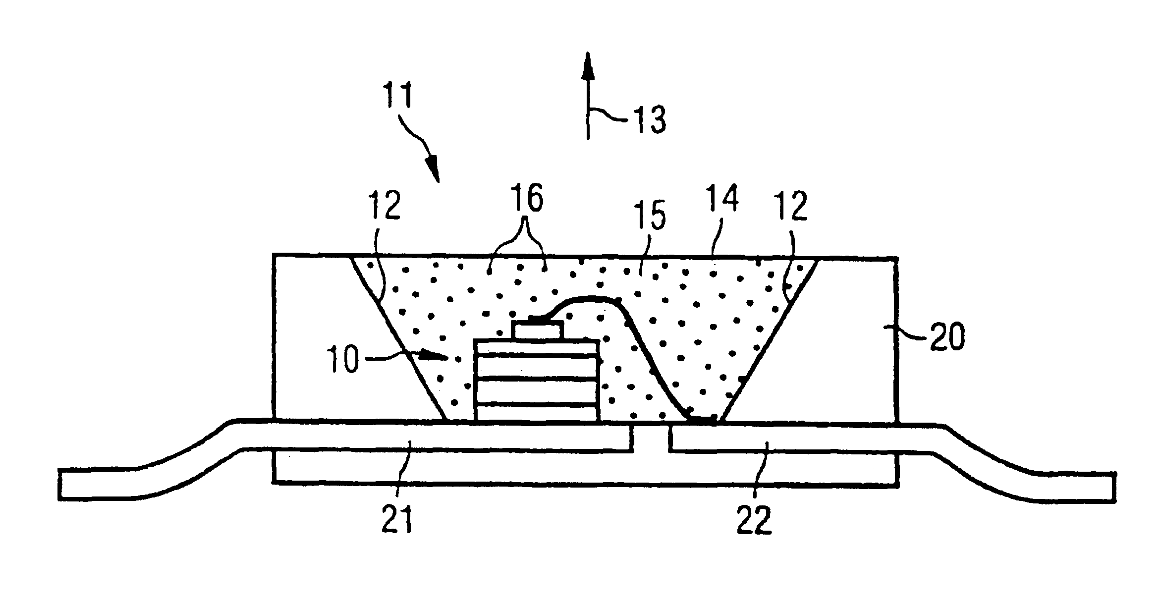
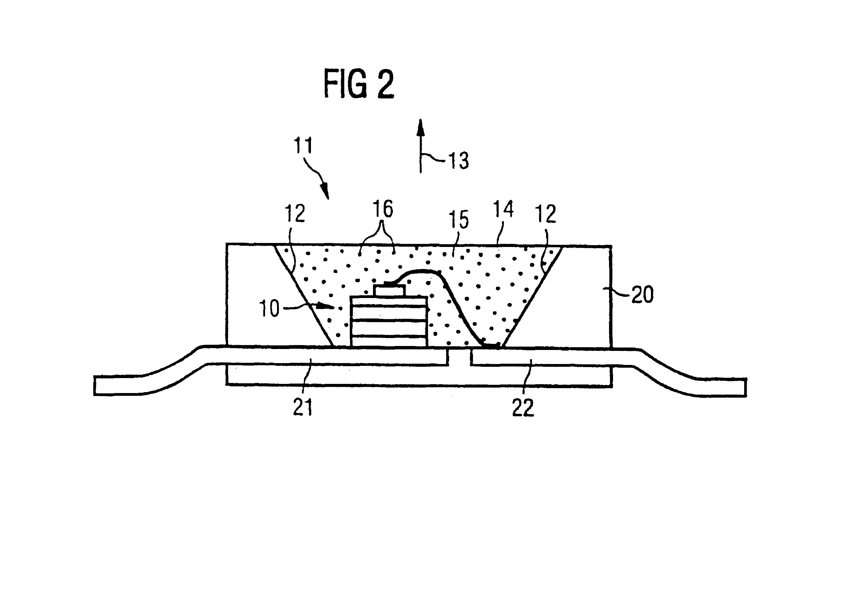
The present invention provides an arrangement of luminescent materials that can be quickly and easily produced based on optimization parameters. These materials are especially useful for light sources emitting in the short-wave optical region of the spectrum, especially in the blue or near-ultraviolet spectral regions. The luminescent materials are cerium-doped garnet structures, specifically A3B5O12, which can be activated by cerium. The use of these materials in a light source requires a wavelength converter and a light source, such as a blue or near-ultraviolet LED. The luminescent materials absorb light in the range of 420 to 490 nm and can be excited by blue light. The position of the absorption and emission bands of the luminescent materials can be adjusted through the choice of rare-earth metals. The luminescent materials are especially useful in white-light-emitting LED components. The invention provides a simple and effective solution for producing luminescent materials for use in light sources.

Problems solved by technology

Finally, it is difficult to optimize the luminescent material in terms of its absorption maximum relative to the peak value of the emission from the light emitter.

Method used


Image

  • Luminescent array, wavelength-converting sealing material and light source
  • Luminescent array, wavelength-converting sealing material and light source
  • Luminescent array, wavelength-converting sealing material and light source

Examples


Embodiment Construction

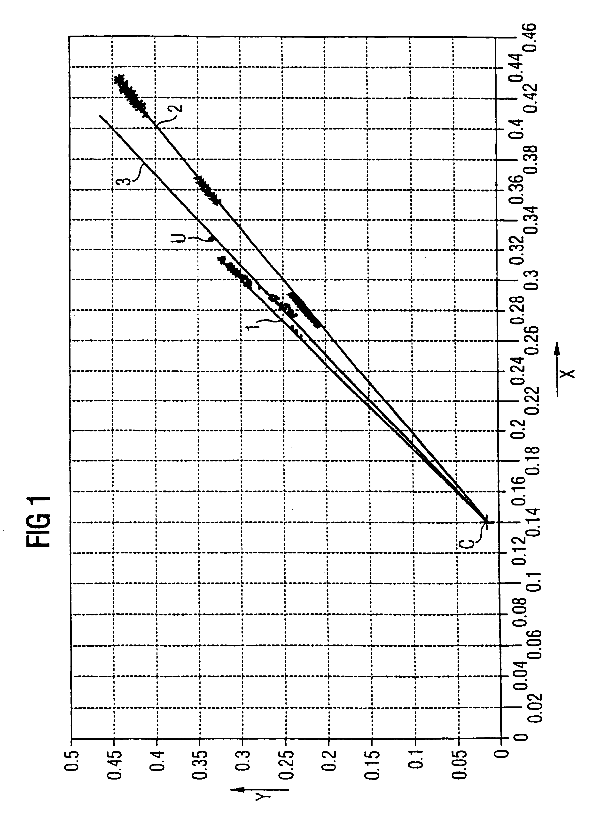
[0042]FIG. 1 illustrates a color locus diagram in which the abscissa is color locus coordinate X of the CIE chromaticity diagram and the ordinate is color locus coordinate Y.

[0043]The plot is based on a light-source arrangement for producing white mixed light, as described in WO 97 / 50132, for example.

[0044]The LED is, for example, an InGaN-based LED chip that emits in the blue region of the spectrum and whose color locus point C in the color locus chart is accordingly located at about x=0.14 and y=0.02. Different color locus lines are obtained by mixing the blue light from the LED of color locus C and the emitted light from a luminescent material, for example embedded in a transparent casting resin.

[0045]For instance, if pure YAG:Ce is used as the luminescent material, a color locus line 1 is obtained. When a luminescent material is used in which Y is partially or predominantly replaced with terbium, the resulting color locus line passes below color locus line 1. With the use of a l...


PUM

PropertyMeasurementUnit
wavelength rangeaaaaaaaaaa

Abstract

The invention proposes an arrangement of luminescent materials for excitation by means of a radiation source and involving the use of a luminescent material having a Ce-activated garnet structure A3B5O12, in which the first component A contains at least one element from the group consisting of Y, Lu, Se, La, Gd, Sm and Tb and the second component B represents at least one of the elements Al, Ga and In, and a plurality of the luminescent materials are mixed together. An associated wavelength-converting casting compound and an associated light-source arrangement are further proposed.

Description

BACKGROUND OF THE INVENTION[0001]The invention concerns an arrangement of luminescent materials, an associated wavelength-converting casting compound and an associated light-source arrangement as set forth in the preambles of claims 1, 4 and 9.[0002]It relates in particular to a yellow-emitting or yellow-green-emitting arrangement of garnet luminescent materials for excitation by means of wavelengths in the blue or near-ultraviolet region of the spectrum. The casting compound provided is in particular a cast-resin matrix containing the arrangement of luminescent materials, and the light source is in particular a light-emitting diode (LED) in combination with the arrangement of luminescent materials and the casting compound.[0003]A luminescent material for light sources and an associated light source are known from WO 98 / 05078. The light source employed therein is a garnet of the structure A3B5O12:D, in which the first component consists of at least one of various rare-earth metals a...

Claims


Application Information

Patent Timeline
Patent Type & Authority Patents(United States)
IPC IPC(8): H01J1/62C09K11/02H01J63/04C09K11/78C09K11/08C09K11/62C09K11/77C09K11/80H01L33/50H05B33/14
CPCC09K11/7769C09K11/7774H01L33/502H05B33/14H01L33/504H01L2924/181H01L2224/48091H01L2224/48247H01L2224/73265H01L2924/00014H01L2924/00012C09K11/77
Inventor DEBRAY, ALEXANDRAWAITL, GUNTERKUMMER, FRANZZWASCHKA, FRANZELLENS, ANDRIES
Owner OSRAM OLED
Learn More