Actuator control device

a technology of actuator and control device, which is applied in the direction of program control, electric programme control, instruments, etc., can solve the problem of long delay before the actuator is moved

Inactive Publication Date: 2006-11-07
FORAC LTD
View PDF4 Cites 0 Cited by
  • Summary
  • Abstract
  • Description
  • Claims
  • Application Information

AI Technical Summary

Benefits of technology

[0006]According to the present invention an actuator control device is adapted to delay actuator moveme...

Problems solved by technology

Therefore, if the actuator is a long way from its desired position there will be a small, or no, delay before the actuator...

Method used


Image

  • Actuator control device
  • Actuator control device

Examples


Embodiment Construction

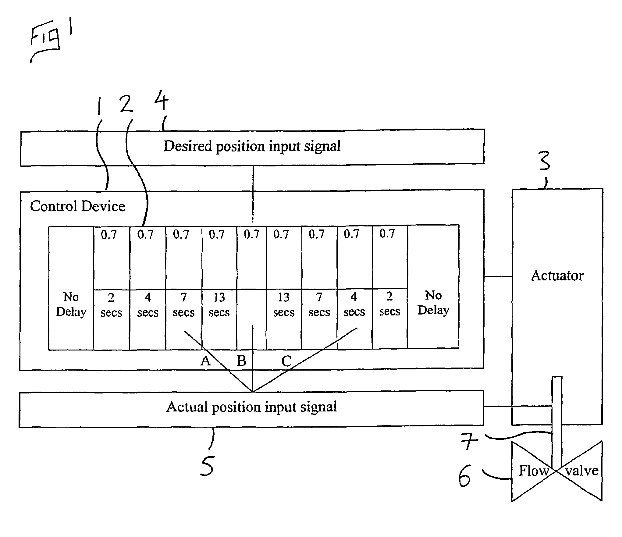
[0019]In FIG. 1 an actuator control device 1 is provided with an electronic program 2 which is adapted to delay the movement of a spring return actuator 3 to a desired position when the actuator's 3 actual position is within a predetermined distance from the desired position.

[0020]The control device 1 is connected to the actuator 3, which is connected to a flow valve 6.

[0021]The control device 1 is provided with a desired position input signal 4, and an actual position input signal 5. The actual position input signal 5 is drawn from the actual position of the valve stem 7 inside the actuator.

[0022]FIG. 1 shows three potential actual position input signals, A, B, and C.

[0023]In use the system operator, or an active pressure monitoring means downstream of the flow valve, provides a Desired position input signal 4. The Control device 1 then moves the actuator to that desired position, at which point the control device begins a timer.

[0024]If the actuator changes position by 1 degree, a...


PUM


Abstract

A valve actuator control device adapted to control the position of a valve actuator by means of solenoid valves, in which if the actuator position deviates from a desired position, but remains within a predetermined distance from said desired position, the control device is adapted to only return the actuator to the desired position after a delay period, thereby to increase the life span of said solenoid valves.

Description

BACKGROUND OF THE INVENTION[0001]This invention relates to an actuator control device for use in particular, but not exclusively, with a pneumatic actuator.[0002]Pneumatic actuators are used to activate valves which control the flow of a substance through a pipe or the like. These actuators may be positioned by means of a control device provided with solenoid valves. Many re-adjustments may be required to obtain a desired valve position, in particular if the desired position is not constant.[0003]A typical electrically operated on / off solenoid valve has a life of approximately 50 million operations. In applications where the flow valves need to be constantly moved, the solenoid valves can expire in less than 12 months.[0004]There are alternative mechanical ways of operating an actuator, however these are more expensive to manufacture and to purchase than those provided with the above described solenoid valves.[0005]The present invention is intended to overcome some of the above prob...

Claims


Application Information

Patent Timeline
IPC IPC(8): G05B19/04G05B19/00G05B19/19G05B19/44
CPCG05B19/00G05B19/19G05B19/44G05B2219/41244G05B2219/41333G05B2219/42226G05B2219/45006
Inventor BUNYARD, ADAM
Owner FORAC LTD
Why Eureka
Try Eureka