
Remote vehicle immobilization

a remote vehicle and vehicle technology, applied in the field of theft deterrent devices, can solve the problems of limiting the operation of the vehicle, the vehicle may be driven away, and the system is not effective in reducing carjacking or reducing, and achieve the effect of limited mobility

Active Publication Date: 2006-10-31
FORD MOTOR CO
View PDF11 Cites 37 Cited by
  • Summary
  • Abstract
  • Description
  • Claims
  • Application Information

AI Technical Summary

Benefits of technology

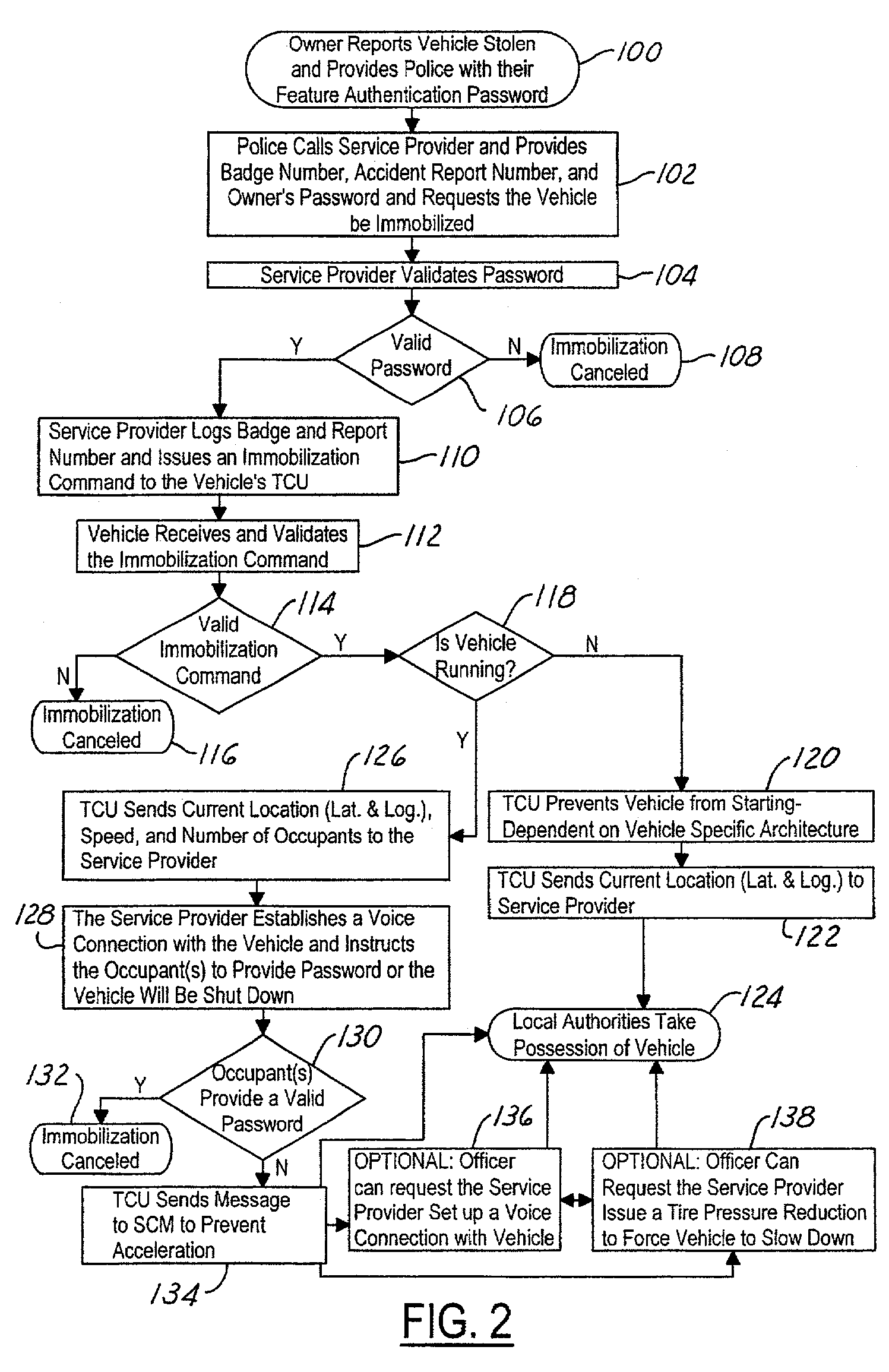
[0009]One advantage of the invention is that the system, once the lower speed limit has been reached, allows the vehicle to have limited mobility to prevent, for example, stopping in an undesirable location such as on a railroad track. Also, the system has safeguards to help insure proper use of the system.

Problems solved by technology

Vehicle anti-theft systems typically sound an alarm upon the unauthorized entry into the automotive vehicle.
Such systems are not effective to reduce carjacking or reduce risks in police pursuit.
That is, once a thief obtains the keys for the vehicle the vehicle may be driven away.
However, once away from the vehicle owner, the proper authorities have no means to restrict the operation of the vehicle.

Method used


Image

  • Remote vehicle immobilization
  • Remote vehicle immobilization
  • Remote vehicle immobilization

Examples


Embodiment Construction

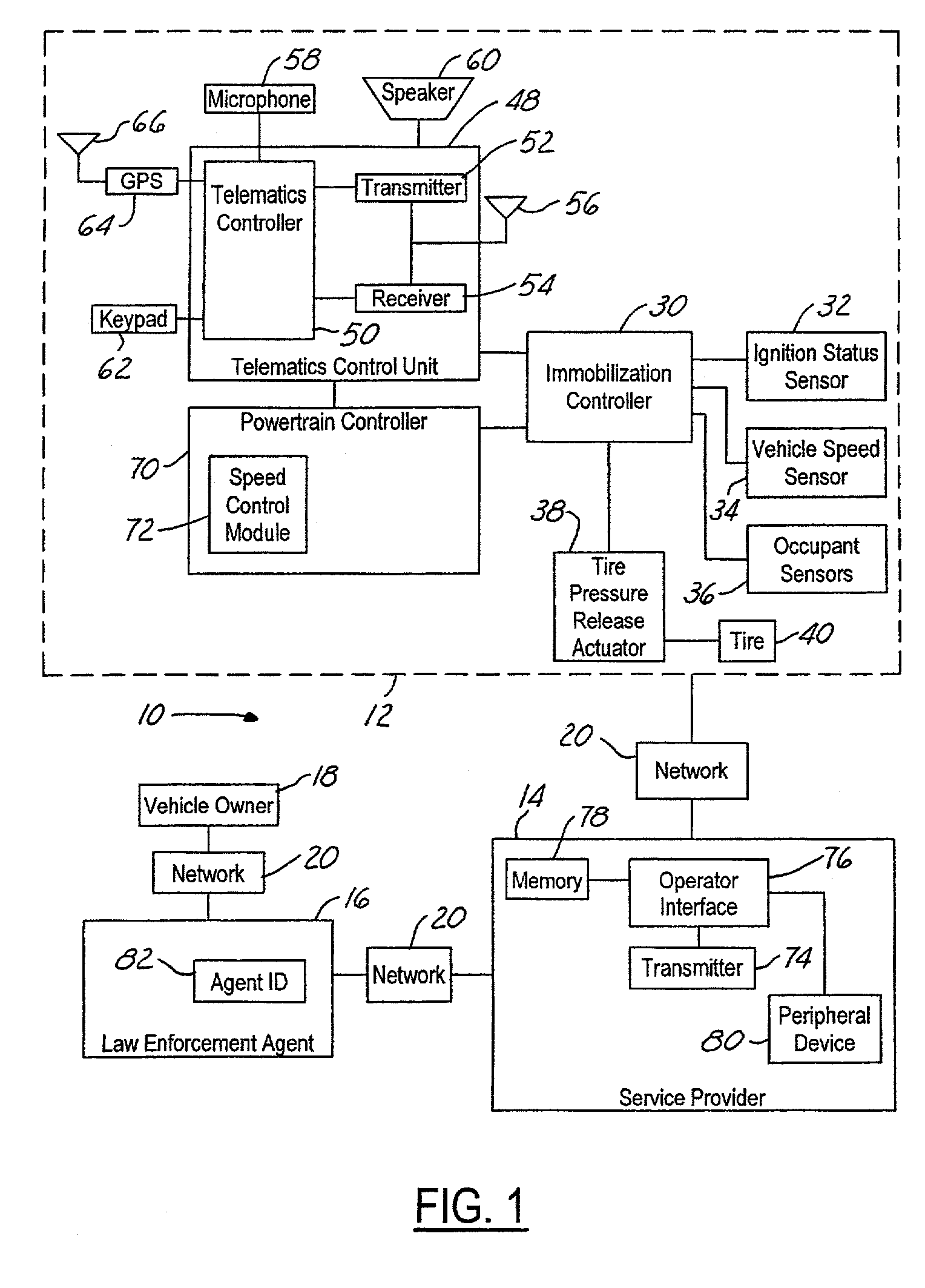
[0014]In the following figures the same reference numerals will be used to illustrate the same components. While specific components are mentioned in the following description, various alternatives will be evident to those skilled in the art. Such variations are not limited to those set forth below.

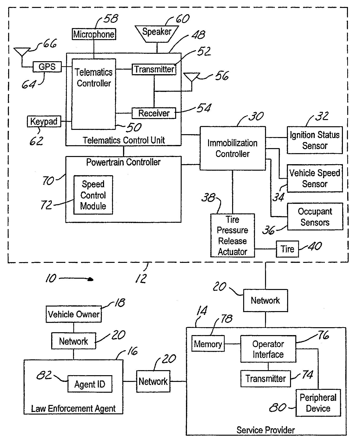
[0015]Referring now to FIG. 1, an immobilization system 10 is illustrated having a vehicle 12, a service provider 14, a law enforcement agent 16, and a vehicle owner 18. The vehicle owner 18, the law enforcement agent 16, the service provider 14, and the vehicle 12 may be interconnected with a network 20. Network 20 may be various types and combinations of networks including a wireless cellular type connection, a satellite connection, public service telephone network, or private telephone network. The interface between vehicle owner 18 and law enforcement agent 16 may also be personal rather than through network 20.

[0016]Vehicle 12 has an immobilization controller 30 that controls the ope...


PUM


Abstract

A vehicle immobilization system (10) is coupled to a network system (20) and includes a vehicle that has a speed sensor (34) generating a vehicle speed signal, a telematics control unit (48) receiving and transmitting signals to and from the network (20), and a speed control module (72). An immobilization controller (30) is coupled to the speed sensor (34), the telematics control unit (48), and the speed control module (72). The immobilization controller (30) receives an immobilization signal from the network (20) and sets a maximum operating speed for the power train controller. When the vehicle speed signal is below the maximum operating speed, the immobilization controller reduces the maximum operating speed within the speed control module until a lower predetermined speed limit is met. The lower speed limit is preferably greater than zero so that some limited mobility of the vehicle may be achieved.

Description

BACKGROUND OF INVENTION [0001]The present invention relates generally to theft deterrent devices for automotive vehicles, and more specifically, to an engine immobilization system that allows rapid recovery of a vehicle.[0002]Vehicle anti-theft systems typically sound an alarm upon the unauthorized entry into the automotive vehicle. Other anti-theft systems provide engine immobilization using an electronic circuit such as a transponder, which in addition to a cut key allows the engine to be started. Such systems are not effective to reduce carjacking or reduce risks in police pursuit. That is, once a thief obtains the keys for the vehicle the vehicle may be driven away. Also, many systems are capable of being bypassed and thus allow the vehicle to be driven away.[0003]Telematic systems are becoming popular items on motor vehicles. Telematic systems include a network connection to a satellite or cellular phone system that allows directions or the like to be obtained. Such systems typ...

Claims


Application Information

Patent Timeline
Patent Type & Authority Patents(United States)
IPC IPC(8): G08C19/00B60R25/04G07C5/00
CPCG07C5/008
Inventor ASLUND, BOPERRY, FRANKAULAKH, GURPREETHELMKE, JAMES W.CUDDIHY, MARK A.GILLENIUS, ULRIKA
Owner FORD MOTOR CO
Learn More