
Cluster sprockets for bicycle transmissions and other prime movers

a technology of clutches and bicycles, applied in the direction of gearing, transportation and packaging, hoisting equipment, etc., can solve the problems of bicyclists losing cadence, chain slippage during derailing, and bicyclists losing control of bicycles

Inactive Publication Date: 2006-10-31
CHATTIN CLUSTER
View PDF4 Cites 13 Cited by
  • Summary
  • Abstract
  • Description
  • Claims
  • Application Information

AI Technical Summary

Benefits of technology

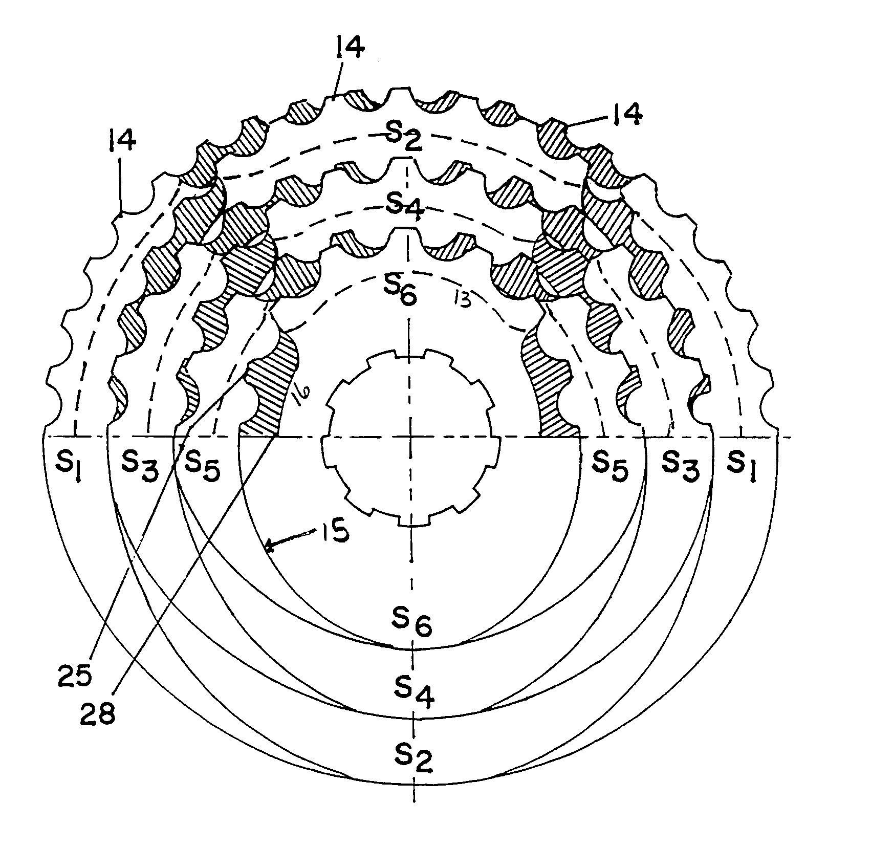
"The present invention provides a sprocket gear that optimizes the derailing of a chain from one sprocket to another, without slippage. The sprocket gear is lightweight, inexpensive to fabricate, and can be easily incorporated into existing bicycles. The sprocket gear includes at least two sprockets axially and concentrically positioned relative to one another, with gear teeth that project axially from the front and back faces of the sprockets. The chain-guiding recesses of the sprockets are positioned to always keep the chain engaged to the system. The sprockets are non-circular in configuration and have at least one long radius and one short radius. The invention also includes a sprocket gear with invention-specific features such as the non-circular configuration of the sprockets, the positioning of the chain-guiding recesses, the alignment of the sprockets, and the use of a wheel axis X."

Problems solved by technology

However, it has also been widely known that the chain may slip during derailing should the teeth of the adjacent sprocket not fully engage the chain as the chain is forcibly moved off the one sprocket onto the adjacent sprocket.
Slippage during shifting is highly undesirable as it causes the bicyclist to lose cadence.
Moreover, chain slippage during a power stroke may cause the bicyclist to lose control of the bicycle and may even result in an accident.
A disadvantage of currently available derailleur systems is that they do not always shift smoothly under load, for example, when a rider is riding a bicycle up a hill.
A further disadvantage of some derailleur type multi-speed transmissions is that a significant amount of force is generally required to shift the chain between adjacent sprockets in one of the sets of sprockets.
Consequently, an expensive and typically power hungry actuator is required.
The result is that electronically controlled automatic derailleur type transmissions have not been widely accepted.
A major problem of the prior art is that the conventional variable speed bicycle uses the conventional sprocket of the single speed bicycle, without taking into consideration the design of the chain shifting process.
As a result, the chance of success of gear changing of the conventional variable speed bicycle is relatively low.
In the meantime, the speed changing process is slow while the operation feel is less smooth.
However, this design is costly, and the split tooth also weakens tooth strength and has negative impact on safety.
Unfortunately, this transmission has not been commercially acceptable, because it is complicated, too heavy, inefficient, and is not well suited to automation with low powered actuators.
A disadvantage presented by the MU patent is that the chain is not always engaged to the teeth, the recesses do not overlap, thus a slip of the chain can occur.
A disadvantage presented by the Chattin patent is that the cluster system does not provide a smooth derailing of the chain from one sprocket to an adjacent sprocket.

Method used


Image

  • Cluster sprockets for bicycle transmissions and other prime movers
  • Cluster sprockets for bicycle transmissions and other prime movers

Examples


Embodiment Construction

[0061]The present invention represents a significant advance over the technology disclosed in U.S. Pat. No. 6,293,884 to the present inventor, the disclosure of which is incorporated in here by reference.

[0062]For the purpose of summarizing this invention, this invention comprises a multi-sprocket gear including a plurality of progressively-sized sprockets that are positioned adjacent to one another so as to define an increasing-diameter sprocket gear. For use in connection with a bicycle or other prime mover, a derailleur or other mechanism is provided to forcibly derail the chain riding on one sprocket to an adjacent sprocket. Upon derailing of the chain from the one sprocket, the chain is engaged by a tooth of an adjacent sprocket and then pulled through a rotational movement such that the chain is fully derailed from the one sprocket to an adjacent sprocket upon one complete revolution.

[0063]In the first preferred embodiment of the present invention, each sprocket of the cluster...


PUM


Abstract

This invention concerns a sprocket gear for facilitating the derailing of the chain of a bicycle transmission and other prime movers. The sprocket gear includes at least two sprockets axially and concentrically positioned relative to one another. Each sprocket includes a perimeter, a front face, and a back face. Gear teeth project axially from at least a first perimeter segment of the front face and at least a second perimeter segment of the front face is free of gear teeth. Gear teeth project axially from the back face perimeter at the at least second segment of the front face. No gear teeth project from the back face perimeter at the at least first perimeter segment of the front face.

Description

BACKGROUND OF THE INVENTION[0001]1. Field of the Invention[0002]The present invention relates generally to a bicycle transmission mechanism, and more particularly, to a multi-speed transmission employing a sprocket gear of the bicycle transmission mechanism that facilitates movement of the chain from one sprocket to an adjacent sprocket during derailing.[0003]2. Description of the Background Art[0004]The bicycle gear-shifting mechanism is generally composed of two sprocket sets and a sprocket chain interconnecting the two sprocket sets for transferring motion from one sprocket to another. The sprocket sets are provided respectively with gears having various numbers of teeth. The gear-changing process of the bicycle is attained by an action of pulling the transmission cable so as to actuate the sprocket chain to move from one sprocket to another.[0005]A derailleur mechanism allows a rider to selectively move the chain to a different one of the sprockets in each set of sprockets. This...

Claims


Application Information

Patent Timeline
Patent Type & Authority Patents(United States)
IPC IPC(8): F16H55/12B62M9/10
CPCB62M9/10Y10T74/1987Y10T74/19884
Inventor CHATTIN, JESSE R.
Owner CHATTIN CLUSTER
Learn More