
Method for mixing fluids

Inactive Publication Date: 2006-10-31
PROPURE AS
View PDF21 Cites 57 Cited by
  • Summary
  • Abstract
  • Description
  • Claims
  • Application Information

AI Technical Summary

Benefits of technology

[0038]The selective absorption of the H2S over the co-absorption of CO2 by the amine results in an improved efficiency of use of the amine. By reducing the co-absorption of CO2, the required level of H2S removal may be achieved with less amine liquid. The reduction in liquid duty will be carried through the regeneration system and will reduce the size of the apparatus required. Both installation and operational costs are significantly reduced. These reductions may be achieved using standard amine solutions and do not require the production of spec

Problems solved by technology

The prior art systems suffer the disadvantage that in order to achieve a significant degree of gas/liquid contact, the columns have to be large and their operation is hampered by excessive foaming.
Also the turn-down ratio of countercurrent contactors is limited due to flooding.
Since the operation may well be carried out under high pressure and since the fluids involved may be highly corrosive, the capital costs of the large columns and subsequent stripping section are high.
Furthermore

Method used


Image

  • Method for mixing fluids
  • Method for mixing fluids
  • Method for mixing fluids

Examples


Example

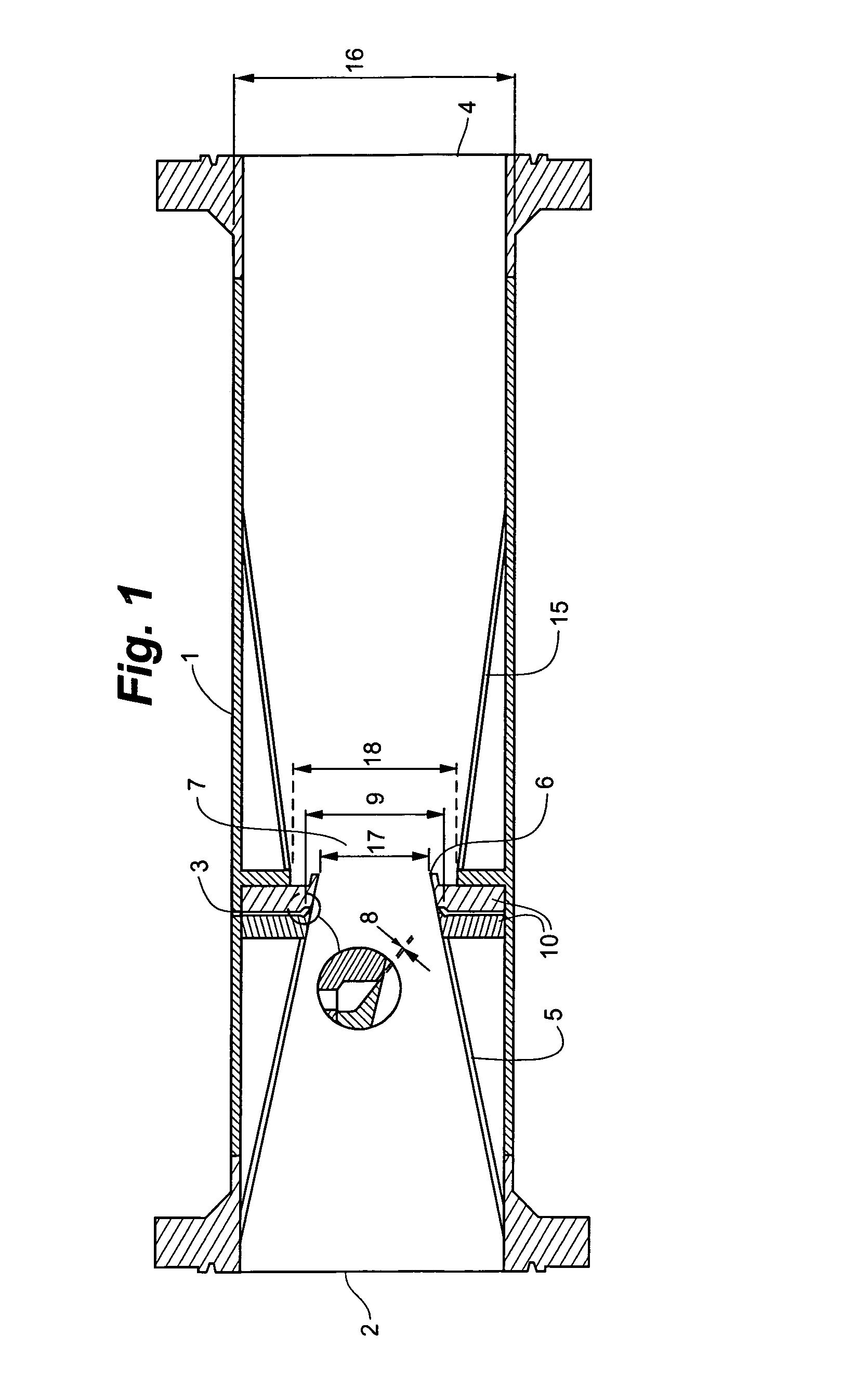
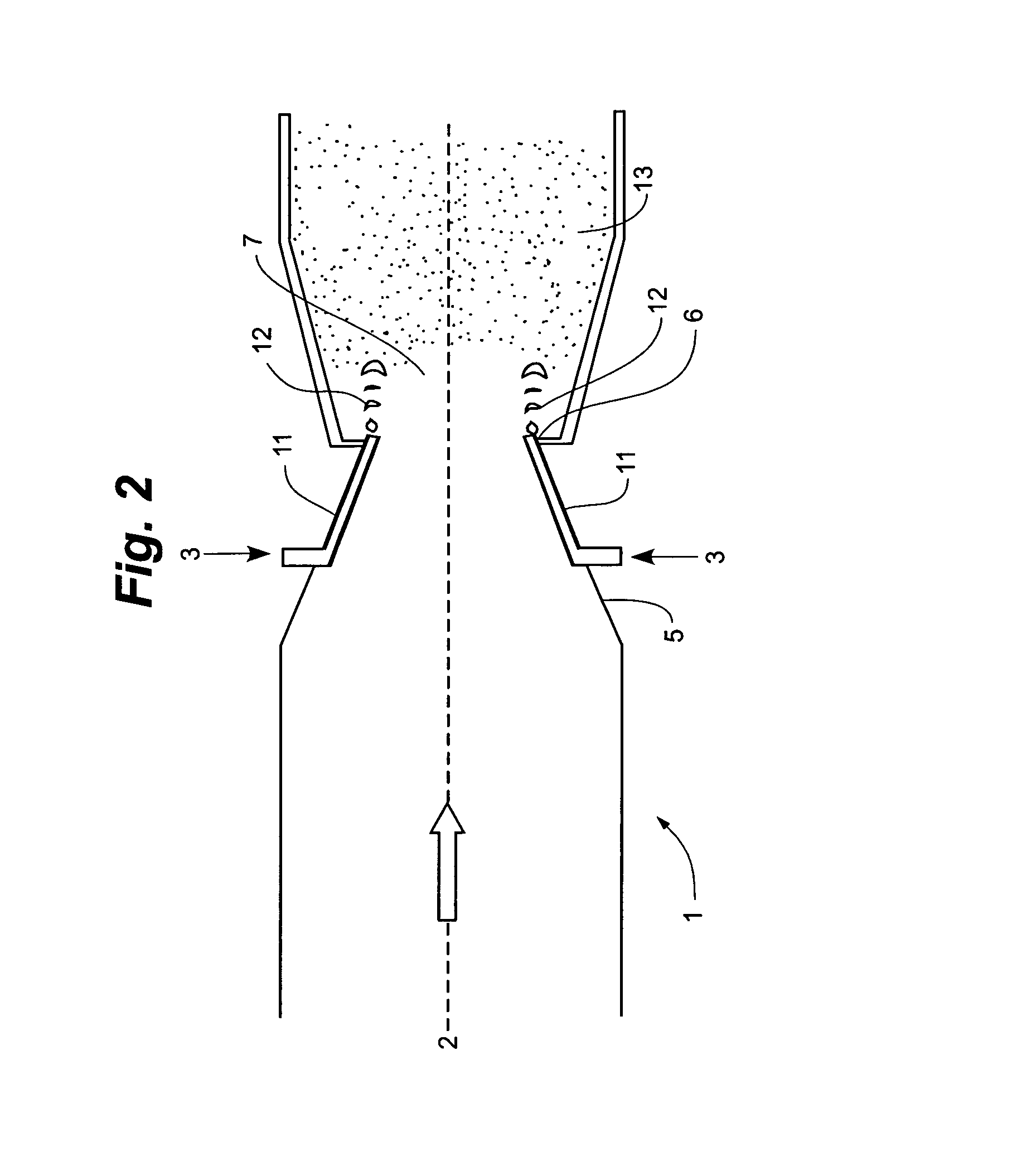
[0059]FIG. 3 shows a second embodiment of a contactor suitable for use in the method of the present invention. Contactor 20 comprises a gas stream inlet 22, a liquid stream inlet 23 and an outlet 24. The gas stream is supplied to the gas stream inlet which leads to a converging pipe section 25 for accelerating the gas stream. At the end of the converging pipe section there is a sharp edge 26 downstream of which there is a reaction zone 27 where the gas and liquid are preferably formed into a homogeneous mixture. One difference between the contactor of FIG. 1 and that of FIG. 3 is the relative location of the liquid inlet to the annulus of liquid. In this case, the liquid is supplied to the inlet 23 from where it passes through the passages 23a and 23b to a reservoir 23c which passes round the circumference of the pipe. The liquid then passes out through the channel 23d which again passes round the whole circumference of the pipe (see FIG. 4) to an annulus on the inner surface of the...


PUM

PropertyMeasurementUnit
Pressureaaaaaaaaaa
Angleaaaaaaaaaa
Homogeneityaaaaaaaaaa

Abstract

The use of a turbulent contactor to absorb a selected gas component from a gas stream. The invention particularly applies to a method of distributing a liquid into a gas stream which comprises providing a liquid to an annulus at the periphery of a pipe in which a gas stream is flowing, the gas flow drawing the liquid into a film along the inner surface of the pipe to a sharp edge at the end of the pipe at which point the liquid breaks off the surface of the pipe and mixes intimately with the gas.

Description

TECHNICAL FIELD[0001]The present invention relates to a method for efficiently mixing two or more fluids, in particular fluids of different phases. The invention also extends to apparatus for carrying out the method. The invention also relates to fluid separation systems, in particular the selective removal of a component or components from a mixture of gases using a liquid solvent or reagent. For example, the present invention may be concerned with the absorption of acid gases such as CO2, H2S, NOx, oxides of sulphur etc. from natural gas and from combustion gases. Another application may be concerned with dehydration of gases by injecting chemicals.BACKGROUND OF THE INVENTION[0002]Conventional systems for the mixing of fluids in different phases employ columns which may be packed columns, plate columns or bubble-cap columns, or columns with some other form of contact medium. In these systems, the various fluids generally flow countercurrently.[0003]The prior art systems suffer the...

Claims


Application Information

Patent Timeline
IPC IPC(8): B05B9/00B01D47/10B01D53/14B01D53/18B01F3/04B01F5/04
CPCB01D53/1462B01D53/18B01F3/04021B01F5/0413B01F5/0428B01F5/0471B01F23/213B01F25/312B01F25/31242B01F25/314231B01F25/314
Inventor NILSEN, FINN PATRICKLINGA, HARALDFANTOFT, RUNENILSEN, INGE SVERRE LUNDEIDE, GEIR INGE
Owner PROPURE AS
Learn More