
Bulk shipping box assembly with detachable pallet

a detachable pallet and shipping box technology, applied in the field of shipping containers, can solve the problems of high equipment cost, high cost of shipping containers and pallets, and safety problems for end users and employees, and achieve the effect of extending the full height and width of the wall and increasing the stacking capacity of the box

Active Publication Date: 2006-10-31
INT PAPER CO
View PDF16 Cites 26 Cited by
  • Summary
  • Abstract
  • Description
  • Claims
  • Application Information

AI Technical Summary

Benefits of technology

The present invention is a bulk shipping box that can be easily attached to a pallet without the need for separate fasteners, and can be quickly and easily erected and detached from the pallet without causing damage to the box or pallet. The box has tabs that can be engaged with the pallet to hold the box to the pallet, and a reinforcing insert that increases the stacking capacity of the box. The box can be made from a single unitary blank of corrugated cardboard, and the attachment to the pallet is secure and easy to use. The technical effects of the invention include improved efficiency in shipment and reuse of the box and pallet, as well as increased stacking strength of the box.

Problems solved by technology

In the former case, shipping the set-up container and pallet is expensive, and in the latter case, the assembly and set up requires added capital cost for equipment, is labor intensive, and presents safety issues for the end user and its employees.
Also, because of the large size of a typical bulk box, it is difficult to reach into the box to apply staples.
Moreover, the staples must penetrate both the box and the pallet, and strapping normally crushes the box.
Both methods require hand tools to apply and remove the fasteners, and cause damage to both the box and the pallet, making re-use impractical.

Method used


Image

  • Bulk shipping box assembly with detachable pallet
  • Bulk shipping box assembly with detachable pallet
  • Bulk shipping box assembly with detachable pallet

Examples


Embodiment Construction

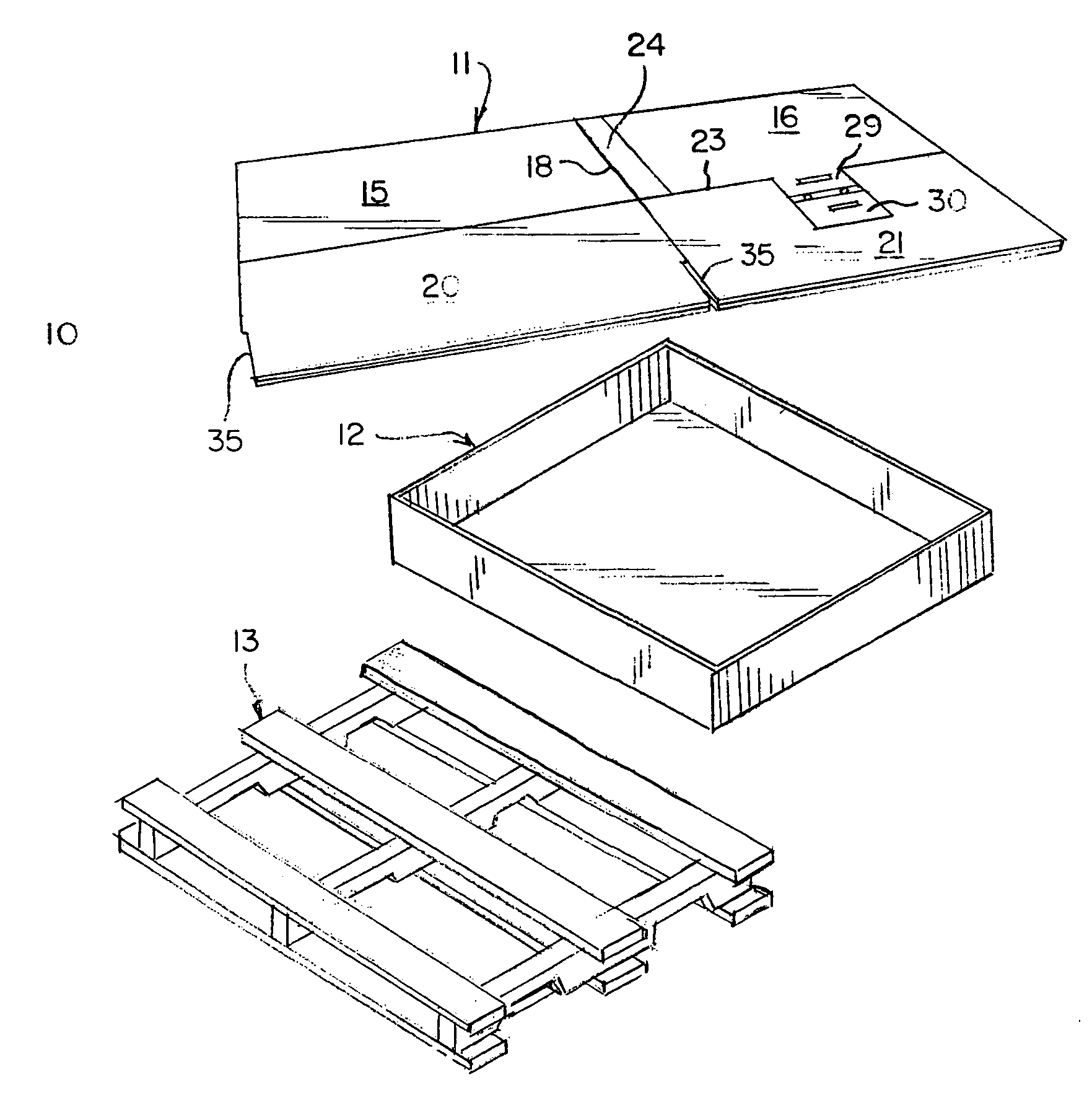
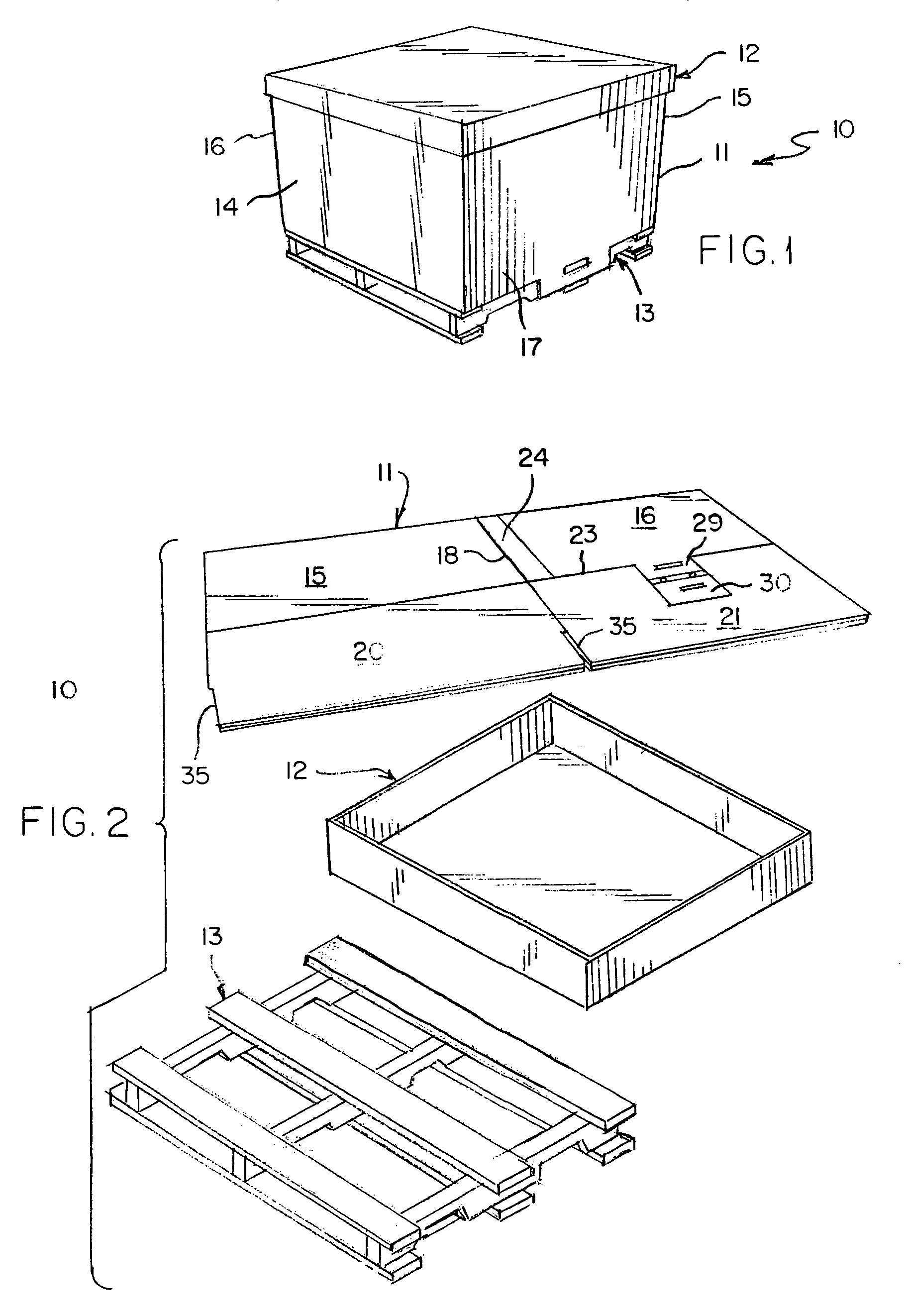
[0049]The bulk shipping assembly of the invention is indicated generally at 10, and as seen best in FIGS. 1 and 2, comprises a box 11, cover 12, and pallet 13. This is the assembly that typically would be manufactured and shipped to an end user in the disassembled, knocked-down flattened condition shown in FIG. 2.

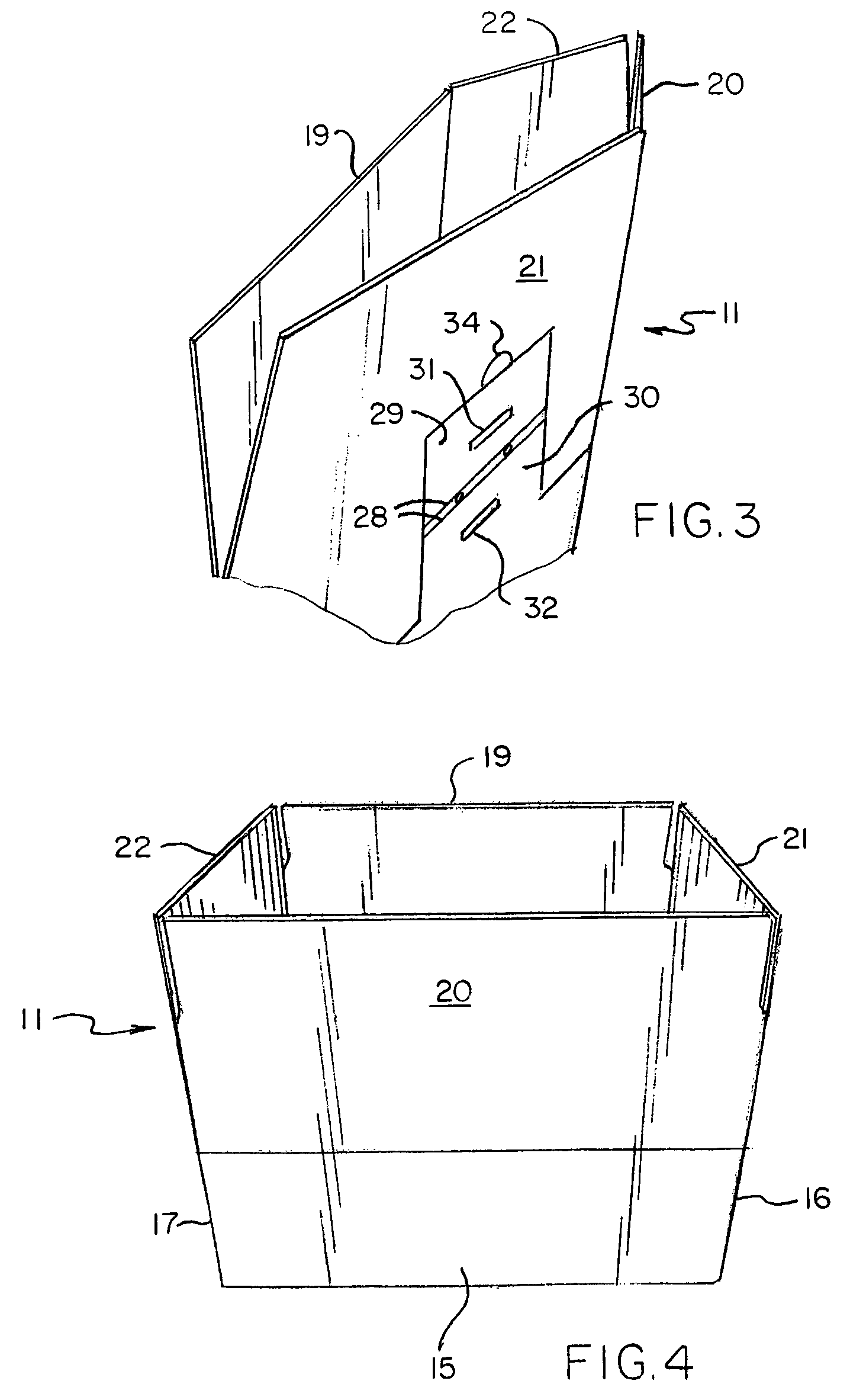
[0050]In a first embodiment of the box of the invention, illustrated in FIGS. 1–17, the box 11 has two opposed side walls 14 and15, and two opposed end walls 16 and 17. With particular reference to FIG. 17, which shows a blank B1 for erecting the first embodiment, the side and end walls are foldably connected to one another along adjacent side edges at fold lines 18, preferably creased. Opposed major bottom flaps 19 and 20 and opposed minor bottom flaps 21 and 22 are foldably attached along fold lines 23, also preferably creased, to bottom edges of respective opposite side and end walls. A glue flap 24 is foldably connected to one side edge of one of the side walls for use ...


PUM


Abstract

A shipping box (11), shipping box and pallet assembly (10), and a blank (B1, B2, B3) for making the shipping box. The box has integral attaching tabs (38) projecting downwardly therefrom, with at least one slot (31, 32) therein for receiving an extended end (41) of at least one slat (40) on a pallet (13), to releasably attach the box to the pallet. A reinforcing insert (70) is placed in the box against opposite walls. The insert has a center panel (77) of the same width and height as the box wall against which it is placed, and double thickness end panels (78) at opposite sides of the center panel, extending perpendicular to the center panel and lying against adjacent box walls.

Description

[0001]This application claims the benefit of prior U.S. Provisional Patent Application Ser. No. 60 / 490,198, filed Jul. 25, 2003.TECHNICAL FIELD[0002]This invention relates to shipping containers for shipping products in bulk, and more particularly to a shipping box and detachable pallet for shipping relatively heavy and bulky items, such as automotive parts and the like.BACKGROUND ART[0003]Heavy duty boxes formed from one or more plies of corrugated cardboard are commonly used for shipping products in bulk. These boxes are frequently fastened to a pallet by staples or straps prior to filling the box with product. The end user must either have the container shipped to it in its set-up condition and already fastened on the pallet, or the end user must have the necessary stapling or strapping equipment available to set up the container in-house. In the former case, shipping the set-up container and pallet is expensive, and in the latter case, the assembly and set up requires added capi...

Claims


Application Information

Patent Timeline
Patent Type & Authority Patents(United States)
IPC IPC(8): B65D19/00B65D3/22B65DB65D19/20
CPCB65D19/20B65D2519/00159B65D2519/00194B65D2519/00273B65D2519/00278B65D2519/00293B65D2519/00323B65D2519/00333B65D2519/00497B65D2519/00597B65D2519/00641B65D2519/00711B65D2519/0091B65D2585/6882Y10S229/918
Inventor BRINGARD, TIMOTHY L.OBERLIESEN, ERIC J.
Owner INT PAPER CO
Learn More