Excavation system and method

a technology of excavating system and keyhole, applied in the field of excavating, can solve the problems of inability to excavate with the precision required, type of excavation, and hole size, and achieve the effects of safer and more precise keyhole excavation procedure, less vibration, and stable cutting procedur

Inactive Publication Date: 2006-10-31
ENBRIDGE TECH
View PDF17 Cites 5 Cited by
  • Summary
  • Abstract
  • Description
  • Claims
  • Application Information

AI Technical Summary

Benefits of technology

[0009]The present invention overcomes these disadvantages by providing a system and method of cutting a core out of a finished surface for keyhole excavation which results in a stable cutting procedure with less vibration. This makes the keyhole excavation procedure safer and more precise, and allows a larger-depth cutting head to be used in order to penetrate thicker finished surfaces.

Problems solved by technology

This type of excavation is costly, in terms of both the inconvenience which results from having to remove and refinish a large portion of the road, sidewalk or other finished surface, particularly for example on a busy roadway, and the size of the hole which must be repaired following servicing.
However, conventional excavating machinery is incapable of excavating with the precision required to provide only the opening necessary to access the service being repaired.
However, the vertical hydraulic press assembly used to force the cutting head into the finished surface is supported on a horizontal arm which has a single stabilizing point, i.e. at the turret, and it is accordingly difficult to keep the press—and thus the cutter—stable during drilling.
Imperfections in the cutting head and obstructions in the finished surface cause the support arm to vibrate.
These vibrations are transferred to the vertical press, which causes the support arm to shift about the drilling access which in turn causes the vibration to increase.
The resulting instability makes cutting difficult in some cases, and limits the size and depth of the rotary cutter head because a deeper rotary cutter head both causes greater vibration and, due to the greater distance between the cutting edge and the shaft, shifts more under the influence of the vibration.

Method used


Image

  • Excavation system and method
  • Excavation system and method
  • Excavation system and method

Examples


Embodiment Construction

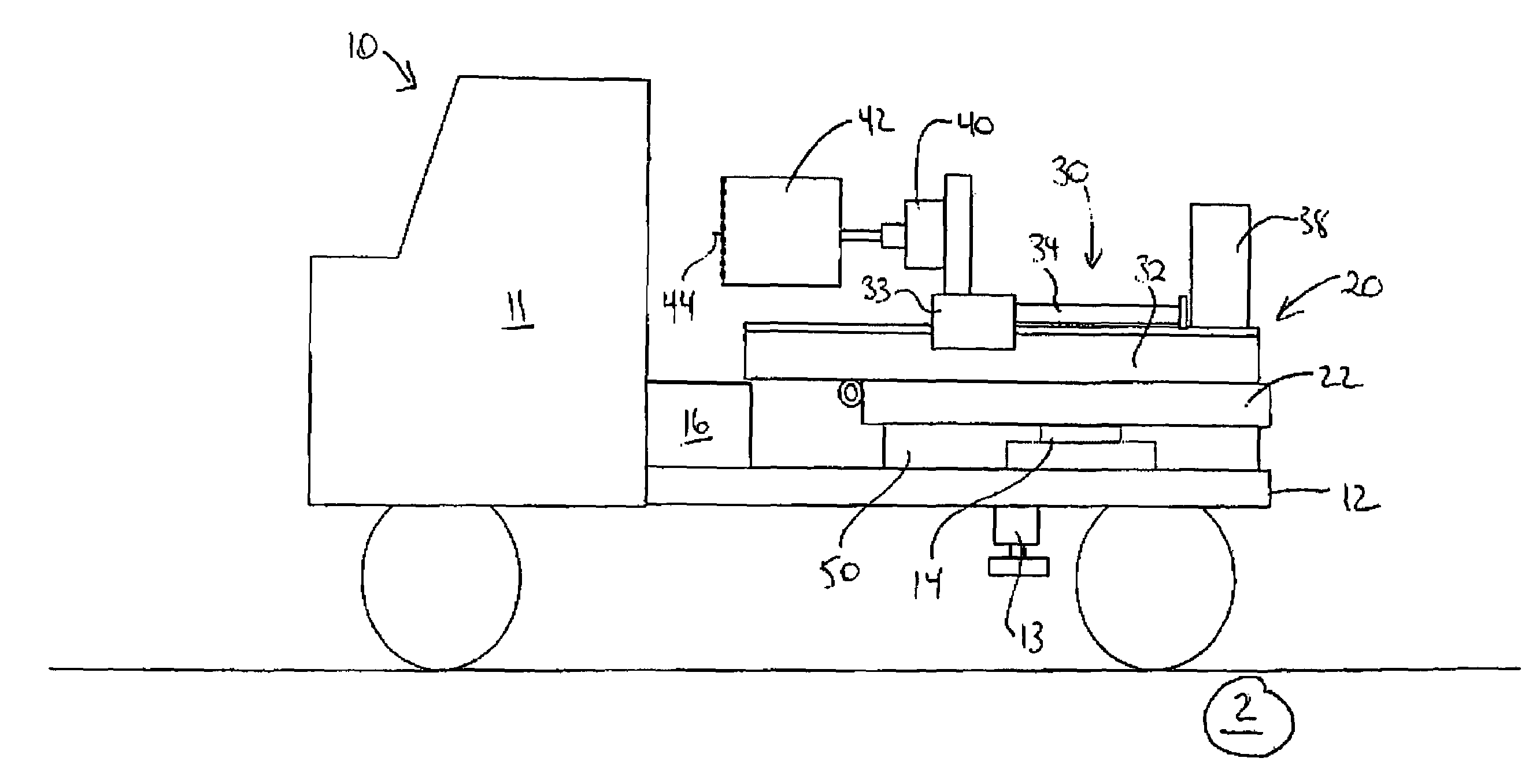
[0024]FIGS. 1 to 3 illustrate a first embodiment of the system of the invention. A truck 10 comprising a back portion, preferably having a flat bed 12, is provided with a rotary turret 14 which supports the cutter assembly 20. The turret 14 is driven by a worm gear (not shown) mounted to the bed 12 understructure and decking, and operated by a built in or remote pendant control (not shown). The hydraulic pump 16 is mounted to the bed 12 immediately behind the cab 11 of the truck 10. The bed 12 is otherwise unobstructed, to allow for a large arc of motion of the cutter assembly 20, as described below.

[0025]The cutter assembly 20 is mounted to the turret 14. The cutter assembly 20 comprises a horizontal support arm 22, which may for example be composed of steel bar or tubing or another suitable material, extending sufficiently beyond the periphery of the truck 10 to support the vertical cutting press 30 (described below) at a position which allows it to clear the rear corners of the b...


PUM


Abstract

A system and method of cutting a core out of a finished surface for keyhole excavation provides a truck with a turret to which a support arm supporting the cutter assembly is mounted, and a stabilizing member remote from the turret, which allows the turret to be rotated about its complete arc of motion while stabilizing the support arm at any desired position about the truck. In a first embodiment the invention comprises an upstanding support rim affixed to or integrated into the bed of the truck. In a further embodiment the invention comprises a support member affixed to the horizontal arm and supported by the truck bed. This makes the keyhole excavation procedure safer and more precise, and allows a larger-depth cutting head to be used in order to penetrate thicker finished surfaces. In the preferred embodiment the cutter head is provided with a pilot which creates a pilot hole in the core that facilitates removal, manipulation and replacement of the core, and improves the integrity of the reinstated core.

Description

FIELD OF THE INVENTION[0001]This invention relates to excavating. In particular, this invention relates to a system and method for excavating a roadway or other finished surface.BACKGROUND OF THE INVENTION[0002]Excavation is a necessary part of the repair procedure for many types of services which run under roadways, parking lots and other finished surfaces, for example a gas or water line running underneath a road or sidewalk. Traditionally, a jackhammer or trimack are used to break up the concrete or asphalt and an excavating machine such as a backhoe would remove the surface cover and uncover the service requiring maintenance and repair. The repair or other servicing would be effected, the excavation backfilled, and the surface refinished using a comparable material (asphalt, concrete, etc. as required to blend in with the surrounding surface finish).[0003]This type of excavation is costly, in terms of both the inconvenience which results from having to remove and refinish a larg...

Claims


Application Information

Patent Timeline
Patent Type & Authority Patents(United States)
IPC IPC(8): A01B13/00E01C23/09
CPCE01C23/094
Inventor MCGIVERY, JOHN W.
Owner ENBRIDGE TECH
Why Eureka
Try Eureka