System for performing coupled finite analysis

Active Publication Date: 2006-10-24
NORTHROP GRUMMAN SYST CORP
View PDF26 Cites 141 Cited by
  • Summary
  • Abstract
  • Description
  • Claims
  • Application Information

AI Technical Summary

Benefits of technology

[0013]Accordingly, an object of the present invention is to provide a finite analysis modeling system that permits the user to identify a joint problem for a coupled solution through the use of a graphical user interface or a scripting language.
[0016]Yet another object of the invention is to facilitate user-specified complex solutions without requiring the user to understand all aspects of each discipline.

Problems solved by technology

A problem exists in the field of finite analysis modeling because engineering specialties do not encompass a wide array of specialized problems that are presented by complex physical situations.
For example, the burning of a solid fuel rocket motor presents a multifaceted problem including structural mechanics, material properties, internal ballistics, chemical reactions, heat transfer, crack combustion, and fracture mechanics.
Typically, such an engineer is not trained in more than one or two of the specialty problem areas and is often incapable of running models in areas outside his or her area of expertise.
Very few, if any, engineers succeed in acquiring the training that is required to model all aspects of this problem, and a team of modelers often is required to produce modeling results through a laborious process involving the transfer of model results between different engineers and / or finite analysis codes.
This segregation of problems exists, in part, due to the lack of overlap in specialty areas as described above, but it also exists because the situations encountered for actual modeling purposes are very diverse and require flexibility if the model is to have optimum results.
A great deal of effort may be expended to develop a comprehensive model where the usefulness of the model diminishes with its complexity.
This sharing of data leads to additional problems.
An engineer receiving model results from another engineer for further processing does not necessarily understand the model results that he or she has received, and this circumstance can lead to computational error.
For example, the preceding engineer may provide results from a less thorough model than is required for optimum results in subsequent calculations, or problems may arise through the nodes of meshes being at different locations when data is passed from a first model to a second model.
Special problems also arise when an engineer receives prior calculation results and uses them as input in a subsequent model addressing a different problem because subsequent calculation results may affect input for the prior model.
The volume changes from the structural mechanics solution have significant effects upon the internal ballistics results which, in turn, affect the structural mechanics model.
Furthermore, the respective modelers may even be unaware that their individual model or an aspect of their model results can affect other models that provide results including input data for subsequent models.

Method used


Image

  • System for performing coupled finite analysis
  • System for performing coupled finite analysis
  • System for performing coupled finite analysis

Examples


Embodiment Construction

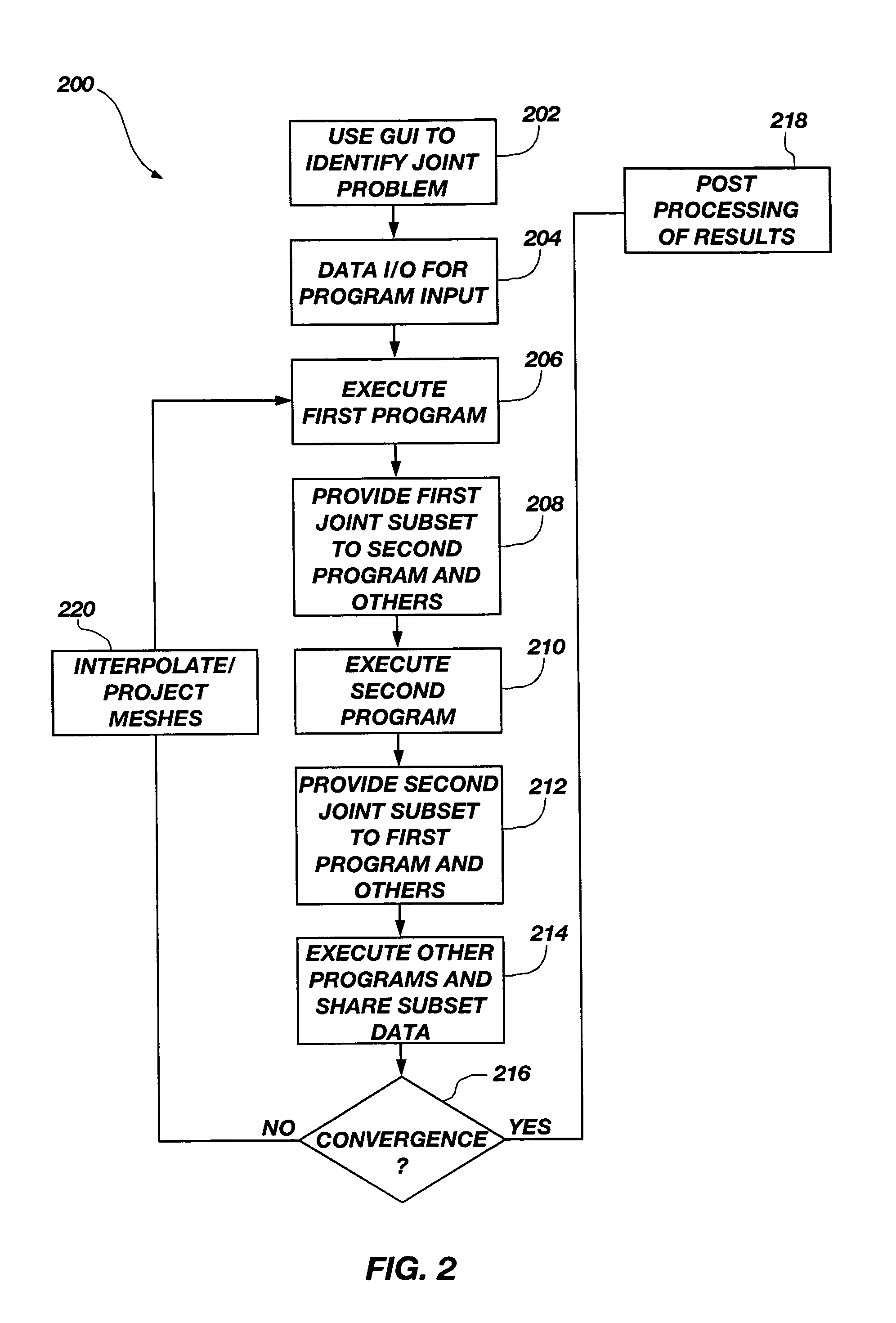
[0033]According to one of the various embodiments of the invention, there is now shown a schematic computer system that is programmed to an electronically configured state through the use of software for the performance of a method, as described above. The system, software and methodology tie or couple together a plurality of finite analysis programs for purposes of solving complex problems while maintaining flexibility through the use of a graphical user interface. By “coupling” it is meant that the results from one finite analytical model are provided to another model as input. For example, the results from a first model may be provided as input to a second model, and the results from the second model may optionally be provided as input to the first model. This process may be repeated until a user-specified convergence is achieved.

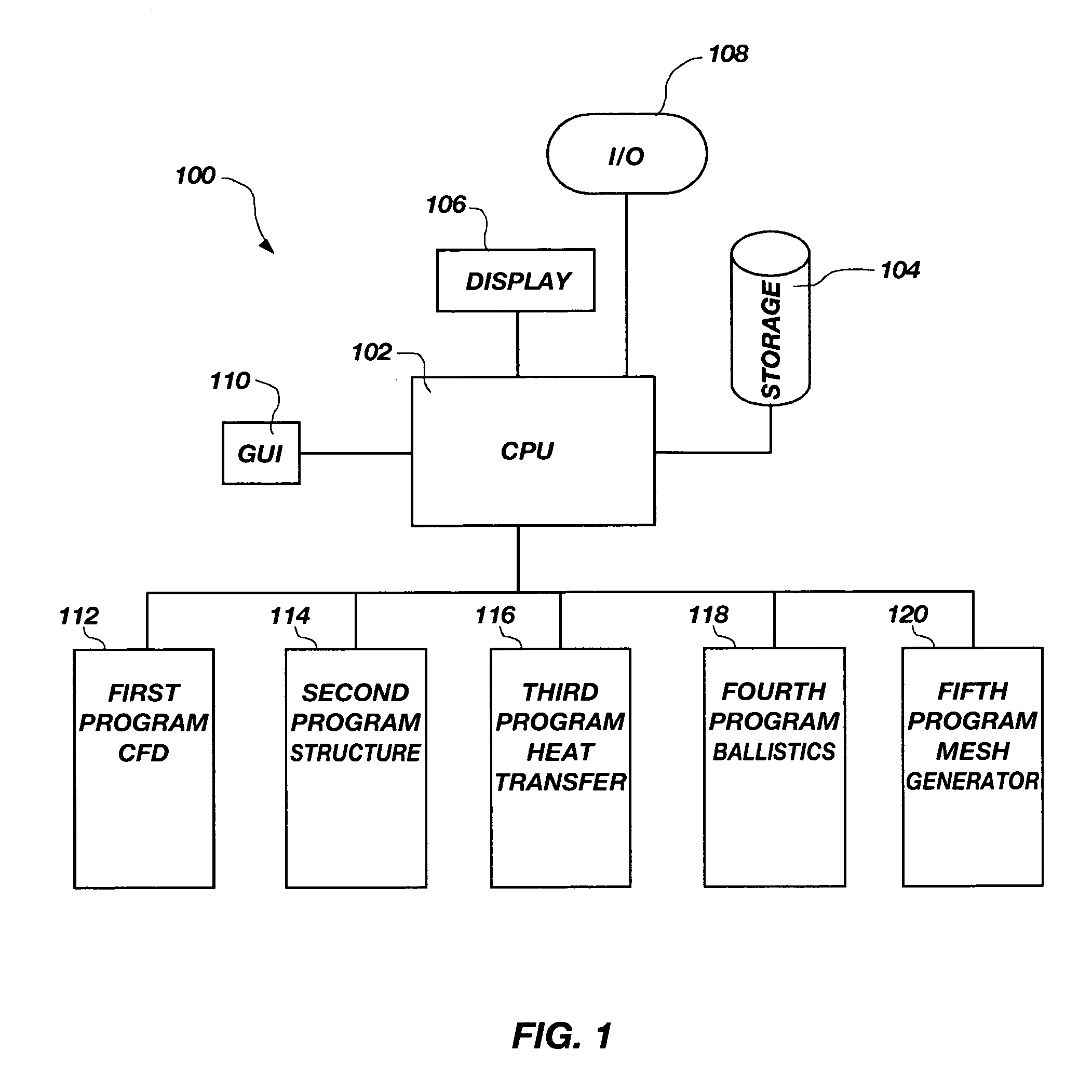
[0034]FIG. 1 depicts a schematic diagram of a computer system 100 including a central processing unit (CPU) 102 that is linked to a magnetic or optical ...


PUM


Abstract

A graphical user interface, together with a comparable scripting interface, couples a plurality of finite element, finite volume, or finite difference analytical programs and permits iterative convergence of multiple programs through one set of predefined commands. The user is permitted to select the joint problem for solution by choosing program selections. Data linkages that couple the program are predefined by an expert system administrator to permit less skilled modelers access to a comprehensive and multifaceted solution that would not be possible for the less skilled modelers to complete absent the graphical user interface.

Description

CROSS-REFERENCE TO RELATED APPLICATION[0001]This application claims priority to U.S. Provisional Patent Application Ser. No. 60 / 246,399, filed Nov. 7, 2000, now abandoned.BACKGROUND OF THE INVENTION[0002]1. Field of the Invention[0003]The invention pertains to the field of software, computer systems and related methods including models that operate through the use of finite analysis, finite volume, and / or finite difference techniques.[0004]2. Description of the Related Art[0005]Finite element, finite volume, and finite difference modeling techniques can generally be described as mathematical approximations of often-complex problems that represent physical behavior. The mathematical models are useful in designing physical apparatus or systems and in predicting the behavior of existing apparatus or systems. These models use a mesh or grid that is superimposed over the system being studied to provide a plurality of cells or elements. These elements may be modeled in multiple dimensions...

Claims


Application Information

Patent Timeline
IPC IPC(8): G06F17/10G06F13/00
CPCG06F17/5018G06F2217/16G06F30/23G06F2111/10
Inventor IVERSON, MICHAEL P.ISAAC, DARON A.
Owner NORTHROP GRUMMAN SYST CORP
Why Eureka
Try Eureka