
Strobe illumination

a technology of strobe light and illumination system, which is applied in the field of strobe light, can solve the problems of improper illumination of workpieces, improper mixture, and not all light sources of illumination system can be operated at their maximum intensities, so as to reduce (if not eliminate) artifacts and minimize blurring

Active Publication Date: 2006-10-24
MITUTOYO CORP
View PDF2 Cites 4 Cited by
  • Summary
  • Abstract
  • Description
  • Claims
  • Application Information

AI Technical Summary

Benefits of technology

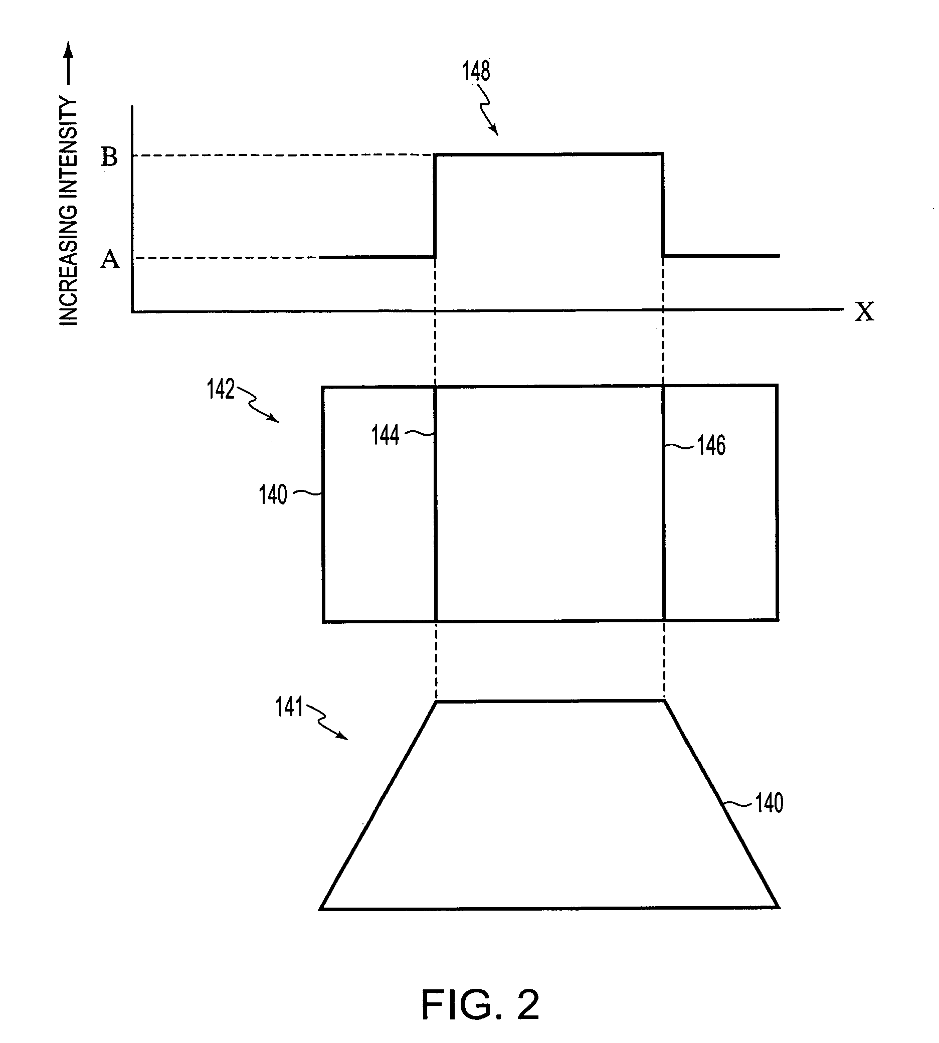
[0006]Strobe lighting may be used to minimize blurring caused by workpiece motion during image capture. A short strobe duration produces a workpiece motion “freezing” effect and a camera may capture one image per strobe, for example. Light sources illuminating a workpiece may be operated at their maximum allowable intensities so that camera CCD integration times, or at least the effective image exposure times as determined by the lighting, may be minimized. However, typically, not all light sources of an illumination system can be operated at their maximum intensities because, as noted above, edge artifacts or edge-shifting may be created by improper illumination of the workpiece. Improper illumination of the workpiece may include an improper mixture of light intensities from various light sources that are used to illuminate the workpiece. Thus, a proper mixture of light intensities must be maintained to reduce (if not eliminate) artifacts.
[0008]Additionally, the workpiece motion “freezing” accomplished by strobe lighting becomes increasingly imperfect at higher workpiece movement speeds, and at longer strobe durations. This is particularly significant when edge locations are to be determined with refined levels of subpixel precision within an image. Moreover, in many applications, it is desirable to attain, as closely as possible, the same edge location measurement from a strobed image that would be obtained from an image of a workpiece that is not moving relative to the imaging system. Thus, given a practical minimum time for strobe durations and a trend toward ever higher workpiece speeds, it is desirable to implement strobe lighting in such a way that it is possible to compensate for any residual edge-shifting due to any residual blur in a strobed image.

Problems solved by technology

However, typically, not all light sources of an illumination system can be operated at their maximum intensities because, as noted above, edge artifacts or edge-shifting may be created by improper illumination of the workpiece.
Improper illumination of the workpiece may include an improper mixture of light intensities from various light sources that are used to illuminate the workpiece.
Unfortunately, operating light sources at less than their maximum intensities may introduce undesirable light source behavior.
For example, it is more difficult to strobe a light source at a particular intensity intermediate between zero and a maximum intensity.
Thus, variations in spectrum output may cause undesirable artifacts, imaging errors, and / or measurement errors.
Additionally, the workpiece motion “freezing” accomplished by strobe lighting becomes increasingly imperfect at higher workpiece movement speeds, and at longer strobe durations.

Method used


Image

  • Strobe illumination
  • Strobe illumination
  • Strobe illumination

Examples


Embodiment Construction

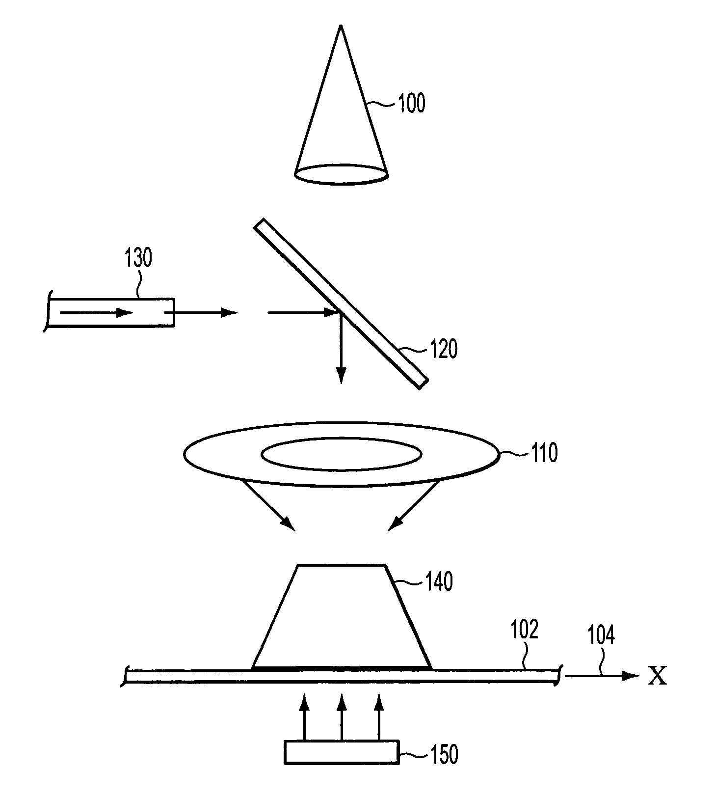
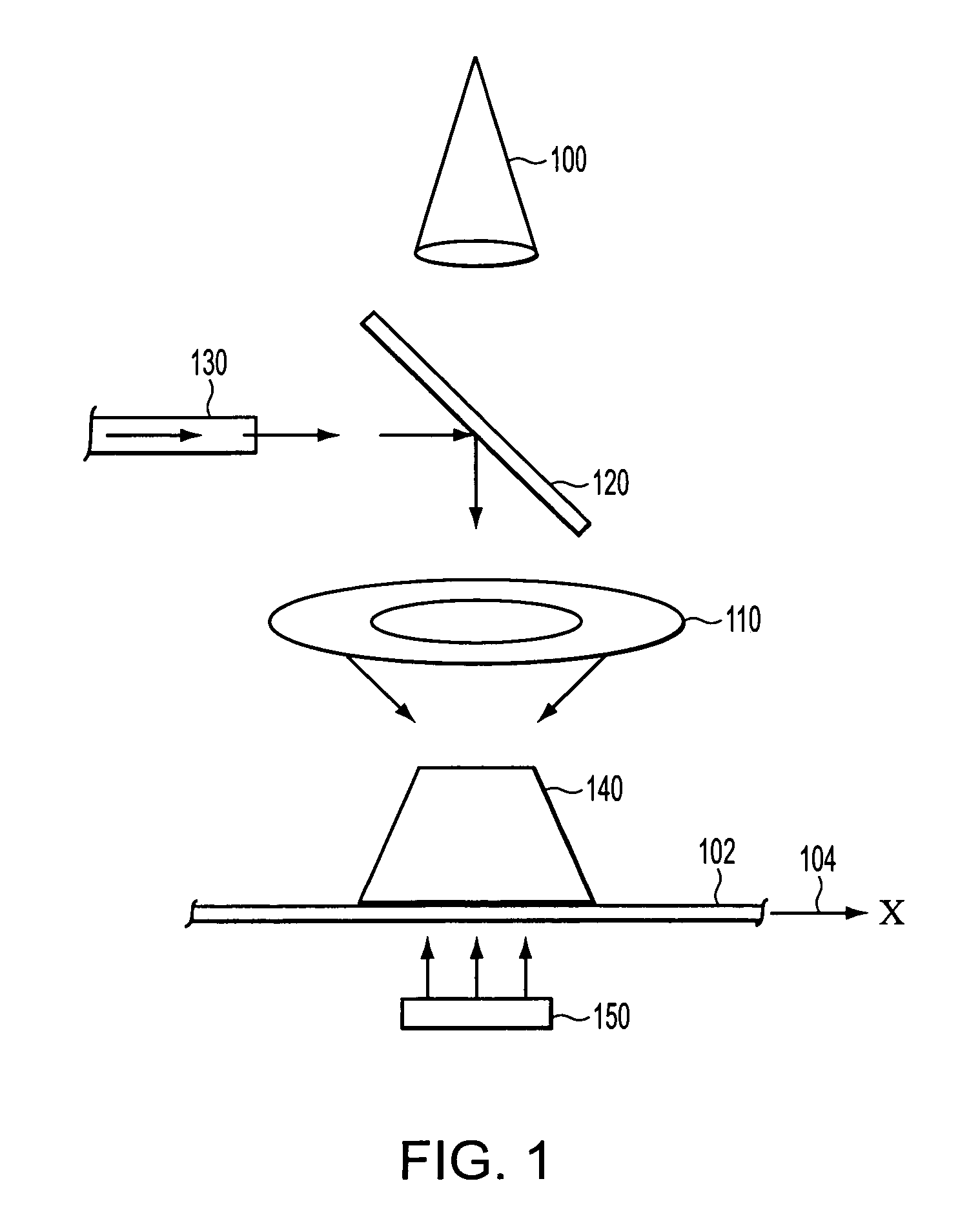
[0032]Micro-strobing may be applied to any machine vision illumination system to achieve desirable, accuracy-enhancing, lighting characteristics. For example, FIG. 1 shows an exemplary lighting system in which the micro-strobing technique may be applied. A workpiece 140 is placed on a moving mechanism such as a transparent stage 102, for example. The transparent stage 102 may comprise a transparent portion of an X-Y stage, a transparent conveyor belt, or the like. A stage light 150, a ring light 110 and a coaxial light 130 together with a half-silvered turning mirror 120 illuminate the workpiece 140. A photodetector 100, such as the CV-A1-20 CCD camera, manufactured by JAI of Copenhagen, Denmark, captures the light reflected from the workpiece 140 to form an image in the form of an array of pixels, for example, that may be processed to identify and inspect relevant features of the workpiece 140. For purposes of explanation, a nominal direction of motion 104, of the workpiece relativ...


PUM


Abstract

An illumination technique is provided that adjusts the respective light intensities of each of a plurality of light sources that are strobed at desirable consistent intensities by adjusting a respective light pulse pattern for each respective light source. All the light sources are controlled to illuminate an object throughout a strobe duration period. The light pulse patterns may be micro-strobed light pulse patterns, formed by a variety of methods. The illumination technique is usable to preserve the general shape of the edge intensity profile on an object, and allow precision edge position measurements, regardless of whether the object is moving or not during image acquisition.

Description

BACKGROUND OF THE INVENTION[0001]1. Field of Invention[0002]This invention is directed to strobe illumination.[0003]2. Description of Related Art[0004]Imaging systems are widely used to inspect workpieces as they are transported through a manufacturing process. Equipment such as machine vision inspection systems often capture images of the workpieces using a camera, for example, and process the captured images to verify various workpiece dimensions by identifying edges of relevant features in the images.[0005]The location where an edge is detected within an array of image data is highly dependent on lighting of the workpiece during image capture. Edge artifacts or edge-shifting may be created by lighting-specific shadows cast due to improper illumination of the workpiece. To increase productivity, workpieces are often kept in motion even during image capture. This places an additional burden on illumination systems to minimize blurring caused by the motion. Such factors frequently l...

Claims


Application Information

Patent Timeline
Patent Type & Authority Patents(United States)
IPC IPC(8): G03B15/02H04N7/18
CPCG01N21/8806G01N21/8901H04N5/2354G03B15/05G01N2021/8838G03B2215/05H04N23/74
Inventor GLADNICK, PAUL G.WASSERMAN, RICHARD
Owner MITUTOYO CORP
Learn More