
Image processing method for automatic image registration and correction

Inactive Publication Date: 2006-10-24
KOREA ADVANCED INST OF SCI & TECH
View PDF7 Cites 17 Cited by
  • Summary
  • Abstract
  • Description
  • Claims
  • Application Information

AI Technical Summary

Benefits of technology

[0013]An object of the present invention for solving the problems in the prior art is to provide an image processing method by which control points are automatically extracted and mismatched control points are then removed from the extracted control points so that image registration and precise image correction can be accurately and accurately performed.

Problems solved by technology

In general, remote sensing data measured from a satellite or aircraft include a great deal of errors and distortions due to an instrument state upon measurement, an atmospheric condition, a moving direction and posture of a platform, a map projection method, and the like.
However, there are still disadvantages in that it is not easy to analyze all the causes of the distortions of the collected image and it is also difficult to precisely correct the distortions of the image in case of severe topographic undulation and high image resolution.
However, there is a disadvantage in that if the control point is incorrectly extracted, the accurate correction result cannot be obtained.
Further, there is inconvenience in that the control point should be obtained again every measuring day even though the same area would be measured.
However, since the operator should initially select and input four or more control points, there still remains a problem of the prior art in that the correction result varies according to the degree of skill of the operator, and much time and higher costs are needed for correcting the image.
These various methods of automatically extracting the control points describes only a process of automatically extracting the control point from the image, but they never suggest or teach a process of finding out and overcoming the errors included in the extracted control points.
According to the aforementioned methods, therefore, the control point can be automatically extracted, but there is also a problem in that it is difficult to perform the accurate image registration and the precise image correction due to the errors included in the extracted control points.

Method used


Image

  • Image processing method for automatic image registration and correction
  • Image processing method for automatic image registration and correction
  • Image processing method for automatic image registration and correction

Examples


Embodiment Construction

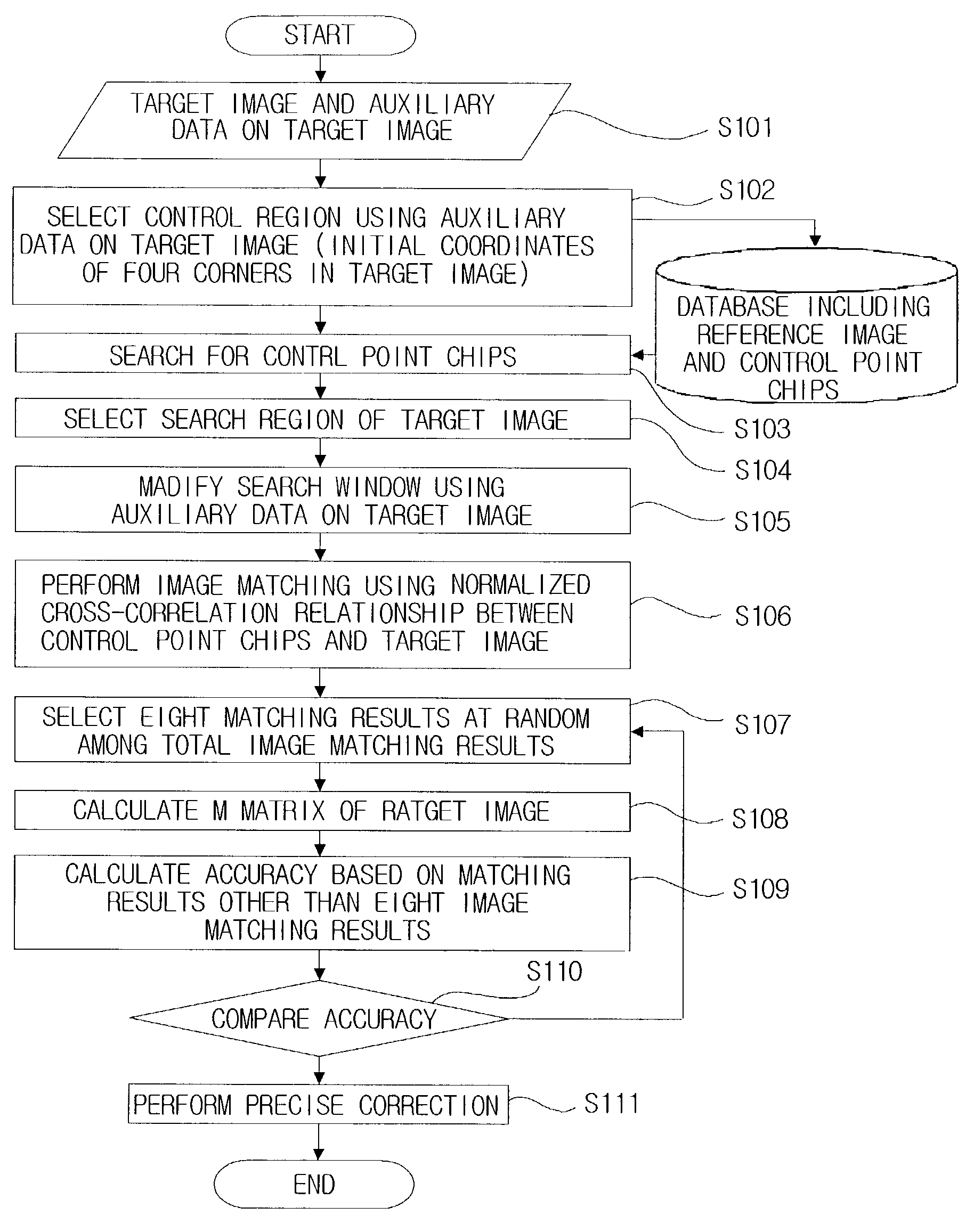
[0022]Hereinafter, a preferred embodiment of an image processing method according the present invention will be explained in detail with reference to the accompanying drawings.

[0023]The present invention is an algorithm running in a general computer system. The general computer system comprises a conventional input / output device, a microprocessor for controlling the system as a whole, a ROM for storing the image processing algorithm of the present invention and providing the microprocessor with the algorithm, a RAM for storing temporary data produced while the microprocessor executes the image processing algorithm of the present invention, and a database for storing data needed for performing the image processing algorithm of the present invention.

[0024]The database includes a reference image, control point chips (CP chips) of the reference image, and auxiliary data. Here, the CP chips mean images which are cut from the reference image in a predetermined size around control points. ...


PUM


Abstract

There is provided an image processing method for use in a computer system having a database for storing a reference image, control point chips (CP chips) of the reference image, and auxiliary data including geographic coordinates, incidence angles and orientation angles of the reference image and the CP chips, comprising the steps of (a) a CP chip extraction step of, when a target image and auxiliary data including location information and incidence and orientation angle information of the target image are inputted, finding out a region of the reference image corresponding to a region including the target image, selecting the found region as a control region, and extracting the CP chips included in the control region of the reference image, (b) an image matching step of searching matching points of the target image for the control points within the CP chips extracted from the CP chip extraction step, (c) a mismatching point removing step of finding out and removing mismatching points among matching results obtained from step (b), and (d) a precise image correction step of arranging the target image into a geographic coordinate system using the matching results obtained after performing step (c).

Description

CROSS-REFERENCE TO RELATED APPLICATION[0001]The present application claims priority from Korean patent application no. 2002-49753, filed Aug. 22, 2002, presently pending.BACKGROUND OF THE INVENTION[0002]1. Description[0003]The present invention relates to a method for processing a satellite image or general image, and more particularly, to a method for automatically performing an image matching process, an image registration and a precise correction process.[0004]2. Background of the Invention[0005]In general, remote sensing data measured from a satellite or aircraft include a great deal of errors and distortions due to an instrument state upon measurement, an atmospheric condition, a moving direction and posture of a platform, a map projection method, and the like. Thus, these errors or distortions should be eliminated or corrected for image restoration. To this end, geometric correction for correcting a difference between a geometric pattern of a collected image and a reference ma...

Claims


Application Information

Patent Timeline
IPC IPC(8): G06K9/00G06K9/20G06K9/64G06T5/00G06T7/00
CPCG06K9/6206G06K9/6211G06T5/006G06T7/0018G06T7/003G06T7/0034G06T7/80G06T7/337G06T7/35G06V10/754G06V10/757G06T5/80G06V10/10
Inventor KIM, TAE JUNGIM, YONG JO
Owner KOREA ADVANCED INST OF SCI & TECH
Learn More