
Around-view image control device and around-view image processing method therefor

Active Publication Date: 2020-08-20
LG INNOTEK CO LTD
View PDF0 Cites 1 Cited by
  • Summary
  • Abstract
  • Description
  • Claims
  • Application Information

AI Technical Summary

Benefits of technology

[0021]The effects of the around-view image control device and the around-view image correction method therefor according to embodiments will be described below.
[0022]According to at least one of the embodiments, since image mismatching is automatically corrected by simply driving a vehicle, it is possible to easily perform image correction.
[0023]According to at least one of the embodiments, it is possible to correct image mismatching without space, time, and place restriction.
[0024]According to at least one of the embodiments

Problems solved by technology

Disabling matching means mismatching.
The same problem may occur in vehicle released without the correction operation.
However, in the related art, in order to perform the correction operation, since the correction pattern is placed in a row on both sides of the ground and then the measured value is obtained from the correction pattern while the vehicle travels, a wide space is required.
In addition, since an operator needs to place the correction pattern on both

Method used


Image

  • Around-view image control device and around-view image processing method therefor
  • Around-view image control device and around-view image processing method therefor
  • Around-view image control device and around-view image processing method therefor

Examples


Example

BEST MODE

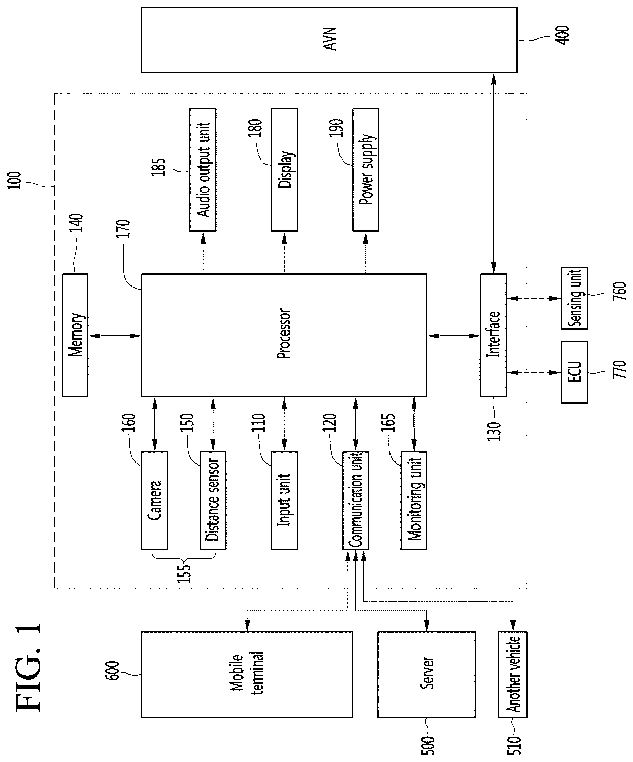
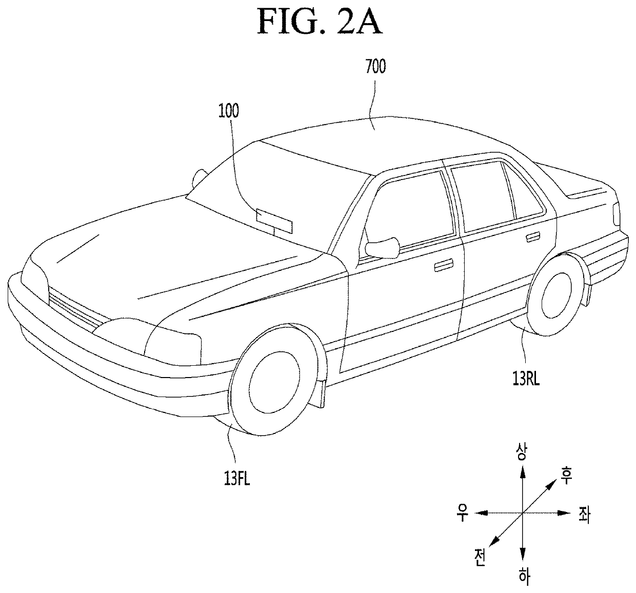
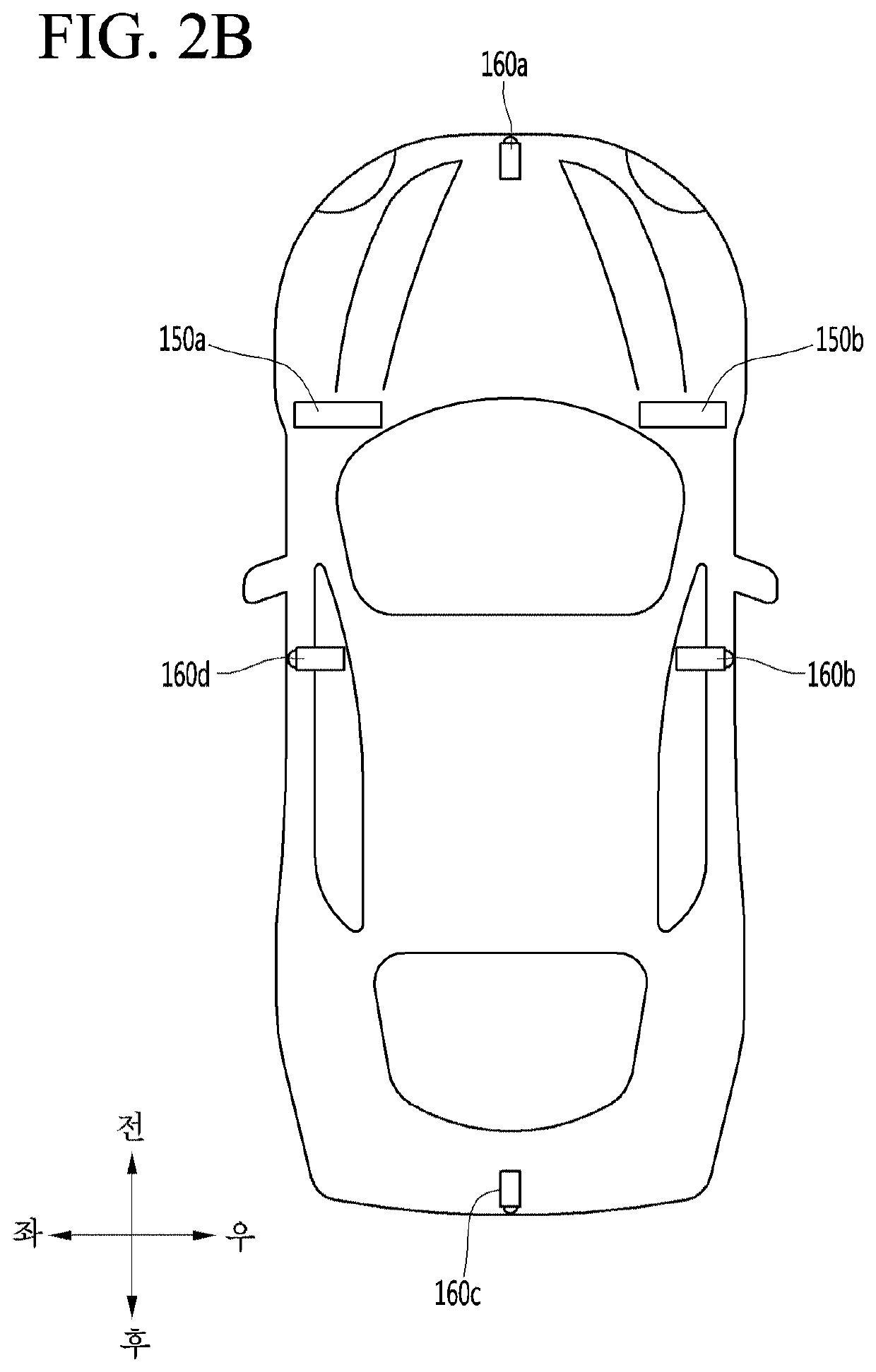
[0048]Description will now be given in detail according to exemplary embodiments disclosed herein, with reference to the accompanying drawings. For the sake of brief description with reference to the drawings, the same or equivalent components may be provided with the same reference numbers, and description thereof will not be repeated. In general, a suffix such as “module” and “unit” may be used to refer to elements or components. Use of such a suffix herein is merely intended to facilitate description of the specification, and the suffix itself is not intended to give any special meaning or function. In the present disclosure, that which is well-known to one of ordinary skill in the relevant art has generally been omitted for the sake of brevity. The accompanying drawings are used to help easily understand various technical features and it should be understood that the embodiments presented herein are not limited by the accompanying drawings. As such, the present disclosu...


PUM


Abstract

An around-view image processing method comprises: generating a first around-view image signal obtained by image synthesis using image information acquired from a plurality of cameras; generating a second around-view image signal obtained by image correction using image information acquired from the plurality of cameras over a predetermined period of time; and outputting the second around-view image signal or outputting the first around-view and second around-view image signals. When the first around-view and second around-view image signals are output, the around-view image processing method may further comprise selecting one image signal from the first around-view and second around-view image signals, and outputting the image signal selected from the first around-view and second around-view image signals.

Description


Claims


Application Information

Patent Timeline
IPC IPC(8): H04N7/18H04N5/247H04N13/243H04N5/232H04N5/262B60R1/00
CPCH04N5/2624H04N13/243B60R2300/607H04N7/181B60R2300/20H04N5/232B60R2300/105H04N5/247B60R1/00B60W40/02B60W50/14H04N17/002B60R2300/602G06T7/73G06T2207/10016G06T2207/30252G06T2207/30244G06V20/56H04N23/698B60W2420/42B60W2050/146H04N23/90H04N23/60
Inventor LEE, SEUNG WON
Owner LG INNOTEK CO LTD
Learn More