
Electronic packages, assemblies, and systems with fluid cooling

a technology of fluid cooling and electronic components, applied in the field of electronic components with fluid cooling, can solve the problems of reducing the performance and reliability of ic's, increasing the heat generated by such ic's to unacceptable levels, and reducing the reliability of ic's

Inactive Publication Date: 2006-10-24
INTEL CORP
View PDF18 Cites 32 Cited by
  • Summary
  • Abstract
  • Description
  • Claims
  • Application Information

AI Technical Summary

Benefits of technology

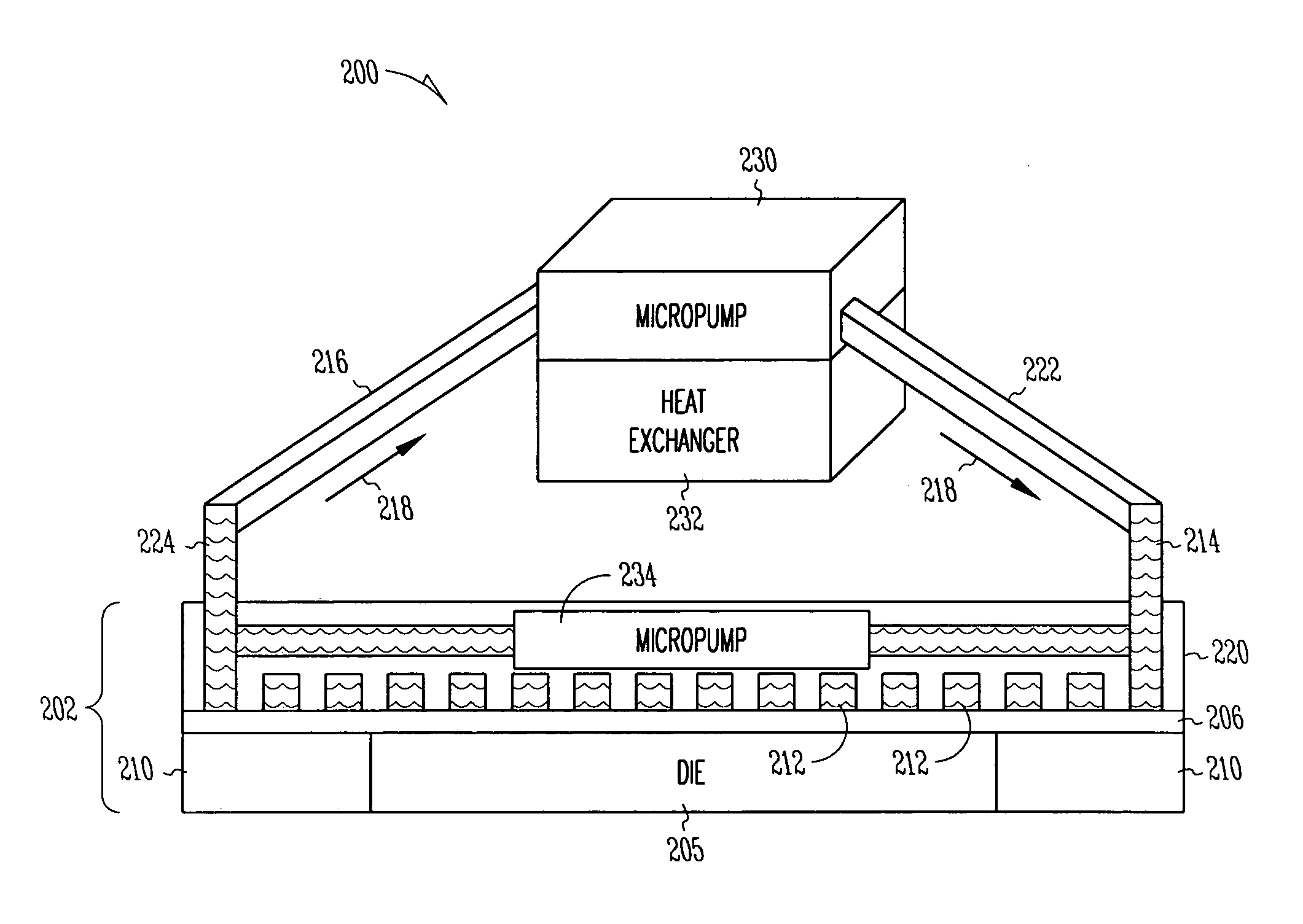
The patent text describes a solution for thermal dissipation problems in electronic systems that have high circuit density and operate at high clock speeds and power levels. The solution involves using a high capacity heat spreader in thermal contact with one or more IC's to dissipate the heat generated by the IC's. The heat spreader may have a fluid-conducting channel formed therein or within it, and a fluid coolant may be circulated through the channel via a pump. The technical effect of this solution is to minimize heat-related issues and improve the performance and reliability of IC's in electronic systems.

Problems solved by technology

As the internal circuitry of IC's, such as processors, operates at higher and higher clock frequencies, and as IC's operate at higher and higher power levels, the amount of heat generated by such IC's may increase their operating temperature to unacceptable levels.
However, the performance and reliability of IC's may diminish as the temperature to which they are subjected increases, so it becomes increasingly important to adequately dissipate heat from IC environments, including IC packages.

Method used


Image

  • Electronic packages, assemblies, and systems with fluid cooling
  • Electronic packages, assemblies, and systems with fluid cooling
  • Electronic packages, assemblies, and systems with fluid cooling

Examples


Embodiment Construction

[0016]In the following detailed description of embodiments of the subject matter, reference is made to the accompanying drawings that form a part hereof, and in which is shown by way of illustration specific preferred embodiments in which the subject matter may be practiced. These embodiments are described in sufficient detail to enable those skilled in the art to practice the subject matter, and it is to be understood that other embodiments may be utilized and that structural, mechanical, compositional, electrical, and procedural changes may be made without departing from the spirit and scope of the subject matter. The following detailed description is, therefore, not to be taken in a limiting sense, and the scope of the subject matter is defined only by the appended claims.

[0017]The subject matter provides a solution to thermal dissipation problems that may be associated with prior art packaging of IC's that have high circuit density and that operate at high clock speeds and high ...


PUM

PropertyMeasurementUnit
thicknessaaaaaaaaaa
thicknessaaaaaaaaaa
tensile strengthaaaaaaaaaa

Abstract

To accommodate high power densities associated with high-performance integrated circuits, an integrated circuit (IC) package includes a heat-dissipating structure in which heat is dissipated from a surface of one or more dice to a heat spreader. The heat spreader has a fluid-conducting channel formed therein, and a fluid coolant may be circulated through the channel via a micropump. In an embodiment, the channel is located at or near a surface of the heat spreader, and a heat-generating IC is in thermal contact with the heat spreader. In an embodiment, the IC is a thinned die that is coupled to the heat spreader via a thinned thermal interface material. Methods of fabrication, as well as application of the package to an electronic assembly and to an electronic system, are also described.

Description

RELATED APPLICATION[0001]This application is related to the following application, which is assigned to the same assignee as the present application:[0002](1) Ser. No. 10 / 036,389, entitled “Thinned Die Integrated Circuit Package”, now issued as U.S. Pat. No. 6,841,413.TECHNICAL FIELD[0003]The subject matter relates generally to electronics packaging and, more particularly, to an electronics package with fluid cooling, and to methods related thereto.BACKGROUND INFORMATION[0004]An integrated circuit (“IC”) die may be assembled into an IC package. One or more IC packages may be physically and electrically coupled to another packaging element, such as a printed circuit board (“PCB”) and / or a heat spreader to form an “electronic assembly”. The “electronic assembly” may be part of an “electronic system”. An “electronic system” is broadly defined herein as any product comprising an “electronic assembly”. Examples of electronic systems include computers (e.g., server, router, desktop, lapto...

Claims


Application Information

Patent Timeline
Patent Type & Authority Patents(United States)
IPC IPC(8): H05K7/20H01L23/473
CPCH01L23/473H01L2924/0002Y10T29/4913H01L2924/00
Inventor HU, CHUANMAHAJAN, RAVI V.
Owner INTEL CORP
Learn More