
Self-locking modular prosthesis

a modular prosthesis and self-locking technology, applied in the field of prosthesis, can solve the problems of affecting the stability of the prosthesis, the inability to precisely locate the upper portion and hence the prosthesis head, and the inability to use a one-piece prosthesis, and achieve the effect of improving the locking characteristics

Inactive Publication Date: 2006-10-17
DEPUY ORTHOPAEDICS INC
View PDF35 Cites 24 Cited by
  • Summary
  • Abstract
  • Description
  • Claims
  • Application Information

AI Technical Summary

Benefits of technology

[0018]It is a further object of the present invention to provide a new and useful method of performing a joint replacement procedure by use of a modular prosthesis.
[0019]It is also an object of the present invention to provide an improved method of performing a joint replacement procedure by use of a modular prosthesis.
[0020]It is yet another object of the present invention to provide a modular prosthesis which has enhanced locking characteristics relative to heretofore designed modular prostheses.
[0022]It is also an object of the present invention to provide a modular prosthesis that provides a high degree of flexibility in regard to the positioning of the head component thereof relative to the patient's acetabulum.

Problems solved by technology

Such a need for prostheses of varying shapes and sizes this creates a number of problems in regard to use of a one-piece prosthesis.
Moreover, since the bow of the stem must conform to the bow of the intramedullary canal of the patient's femur, rotational positioning of the upper portion (i.e. proximal end) of the prosthesis is limited thereby rendering precise locating of the upper portion and hence the head of the prosthesis very difficult.
Such a design allows the distal stem component to be selected and thereafter implanted in the patient's bone in a position which conforms to the patient's anatomy while also allowing for a limited degree of independent positioning of the proximal neck component relative to the patient's pelvis.
One issue that arises as a result of use of a modular prosthesis is the locking of the components relative to one another.
However, such a design has a number of drawbacks associated therewith.
Firstly, functional loading during use of the prosthesis may not provide a positive lock and may actually tend to urge the upwardly extending post of the distal stem component out of the bore defined in the proximal neck component.
This creates a number of problems since many of such functional loads tend to be axial in nature.
In particular, by the nature of its design, axial loads exerted on a fastener such as a screw or bolt bear on the threads of the fastener thereby undesirably exerting a relatively large load to a relatively small surface area.
Over time, such loads may degrade or even breach the mechanical integrity of the threads thereby potentially allowing the components to separate from one another.
Secondly, manufacture of such modular prosthesis is relatively difficult and, as a result, expensive.
Such drilling, often referred to as “gun drilling”, is relatively difficult to do since, amongst other things, it requires adherence to extremely strict tolerances thereby increasing costs associated with manufacture of the modular prosthesis.

Method used


Image

  • Self-locking modular prosthesis
  • Self-locking modular prosthesis
  • Self-locking modular prosthesis

Examples


Embodiment Construction

[0042]While the invention is susceptible to various modifications and alternative forms, a specific embodiment thereof has been shown by way of example in the drawings and will herein be described in detail. It should be understood, however, that there is no intent to limit the invention to the particular form disclosed, but on the contrary, the intention is to cover all modifications, equivalents, and alternatives falling within the spirit and scope of the invention as defined by the appended claims.

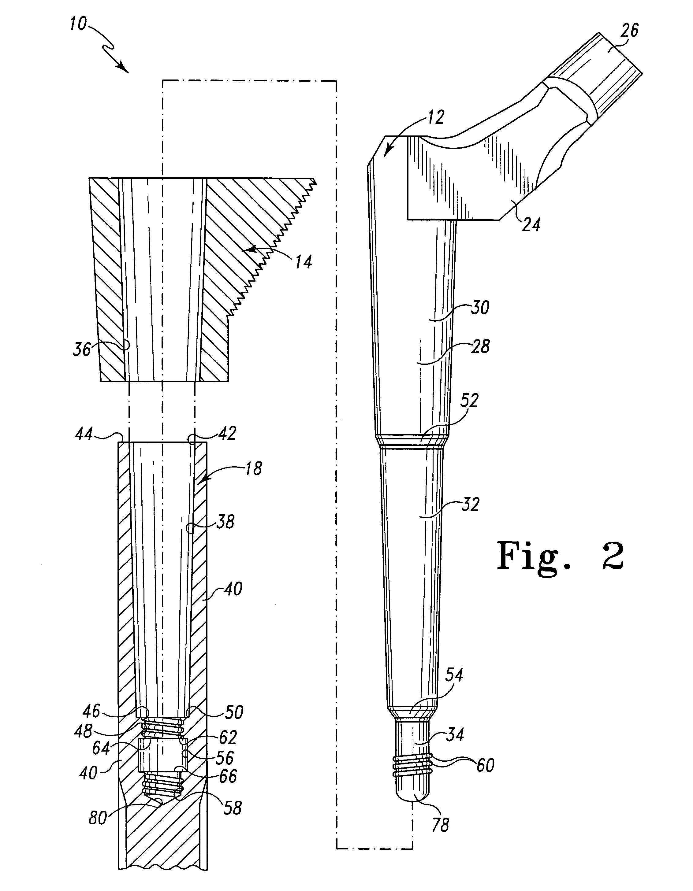
[0043]Referring now to FIGS. 1–3, there is shown a modular prosthesis 10 for use during performance of a joint replacement procedure such as a hip replacement procedure. It should be appreciated that although the present invention is herein exemplarily described in regard to performance of a hip replacement procedure, the concepts of the present invention may be utilized in regard to replacement procedures at numerous other joint locations throughout the body. For example, the concepts ...


PUM


Abstract

A modular prosthesis is disclosed that includes a neck member having a tapered neck body. The modular prosthesis further includes a sleeve component having a first elongated tapered bore. The tapered neck body is received within the first elongated tapered bore so as to taper lock the sleeve component to the neck member. The modular prosthesis also includes a stem member configured to be implanted into a medullary canal of a bone. One of the neck member and the stem member includes a second elongated tapered bore. The other of the neck member and the stem member includes a tapered post that is received within the second tapered bore so as to taper lock the neck member to the stem member.

Description

[0001]This application is a continuation of both (i) application Ser. No. 10 / 032,984, filed on Oct. 23, 2001 now U.S. Pat. No. 6,723,129, and (ii) application Ser. No. 10 / 033,105, filed on Oct. 22, 2001 now U.S. Pat. No. 6,706,072 Each of the above-identified patent applications Ser. Nos. 10 / 032,984 and 10 / 033,105 claims the benefit of U.S. Provisional Application Ser. No. 60 / 246,854, filed Nov. 8, 2000. The disclosures of each of the above-identified provisional and utility patent applications are hereby totally incorporated by reference in their entirety.TECHNICAL FIELD OF THE INVENTION[0002]The present invention relates generally to a prosthesis, and more particularly to a self-locking modular prosthesis.BACKGROUND OF THE INVENTION[0003]During the lifetime of a patient, it may be necessary to perform a joint replacement procedure on the patient as a result of, for example, disease or trauma. The joint replacement procedure may involve the use of a prosthesis which is implanted in...

Claims


Application Information

Patent Timeline
IPC IPC(8): A61F2/30A61B17/56A61B17/58A61F2/00A61F2/02A61F2/28A61F2/32A61F2/36A61F2/46
CPCA61F2/30734A61F2/36A61F2/4607A61F2/30771A61F2/3662A61F2/367A61F2/3676A61F2002/30322A61F2002/30332A61F2002/30354A61F2002/30405A61F2002/30434A61F2002/30512A61F2002/30604A61F2002/30616A61F2002/30736A61F2002/30738A61F2002/30797A61F2002/30813A61F2002/30827A61F2002/30886A61F2002/30904A61F2002/3611A61F2002/3625A61F2002/365A61F2002/3652A61F2002/366A61F2002/3674A61F2002/3686A61F2002/4619A61F2002/4623A61F2002/4629A61F2002/4681A61F2220/0025A61F2220/0033A61F2220/0041A61F2250/0026A61F2002/30433A61F2002/30507A61F2002/3054A61F2/4603
Inventor DWYER, KIMBERLY A.MCCLEARY, LARRY G.DECARLO, ALFRED
Owner DEPUY ORTHOPAEDICS INC
Learn More