
Illuminated protective headgear

a protective head and headgear technology, applied in the field of illumination headgear, can solve the problems of limited headgear, difficult production, and not very eye-catching for consumers, and achieve the effects of superior visual effects and commercial appeal for users, low cost, and simple manufacturing

Inactive Publication Date: 2006-10-17
KUTNYAK MARK
View PDF38 Cites 79 Cited by
  • Summary
  • Abstract
  • Description
  • Claims
  • Application Information

AI Technical Summary

Benefits of technology

[0011]It is a general object of the present invention to produce illuminated protective headgears for a variety of uses that are relatively inexpensive, simple to manufacture and have a low number of components, while having superior visual effects and commercial appeal for the user and the consumer, while retaining the strength of the headgear in resisting impacts.
[0012]A more specific object of the present invention is to improve on the lighting effects of illuminated headgears, by providing a headgear in which various graphical designs may be used in multi-element flashing light displays to show the location of the user by providing a motion effect. In this context, the term “graphical” is intended to exclude mere configurations of alphabetic letters and numerals of a type shown in the prior art and generic geometric shapes such as squares, triangles, and circles.
[0013]The invention can be further enhanced by utilizing multi-colored elements or by operating the light sources to achieve a strobing effect.

Problems solved by technology

Such headgears have been limited to use of large incandescent lights, electroluminescent light strips and more recently to use of small lighting elements such as light emitting diodes (LEDs).
Although each type of illumination process has their advantages and disadvantages, they are for the most part non-cost effective, difficult to produce and not very eye-appealing to the consumer.
As a result these designs have not been widely seen in the recreational field.
Another technical problem in providing illuminated headgears, is retaining the strength of the helmet to impacts.

Method used


Image

  • Illuminated protective headgear
  • Illuminated protective headgear
  • Illuminated protective headgear

Examples


Embodiment Construction

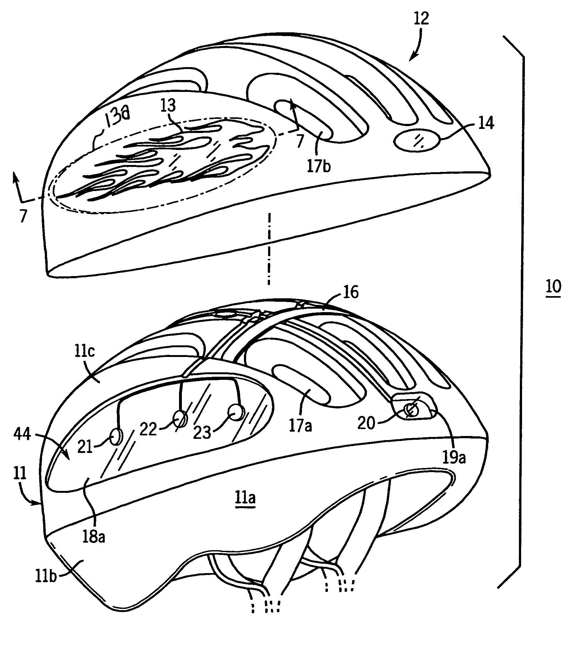
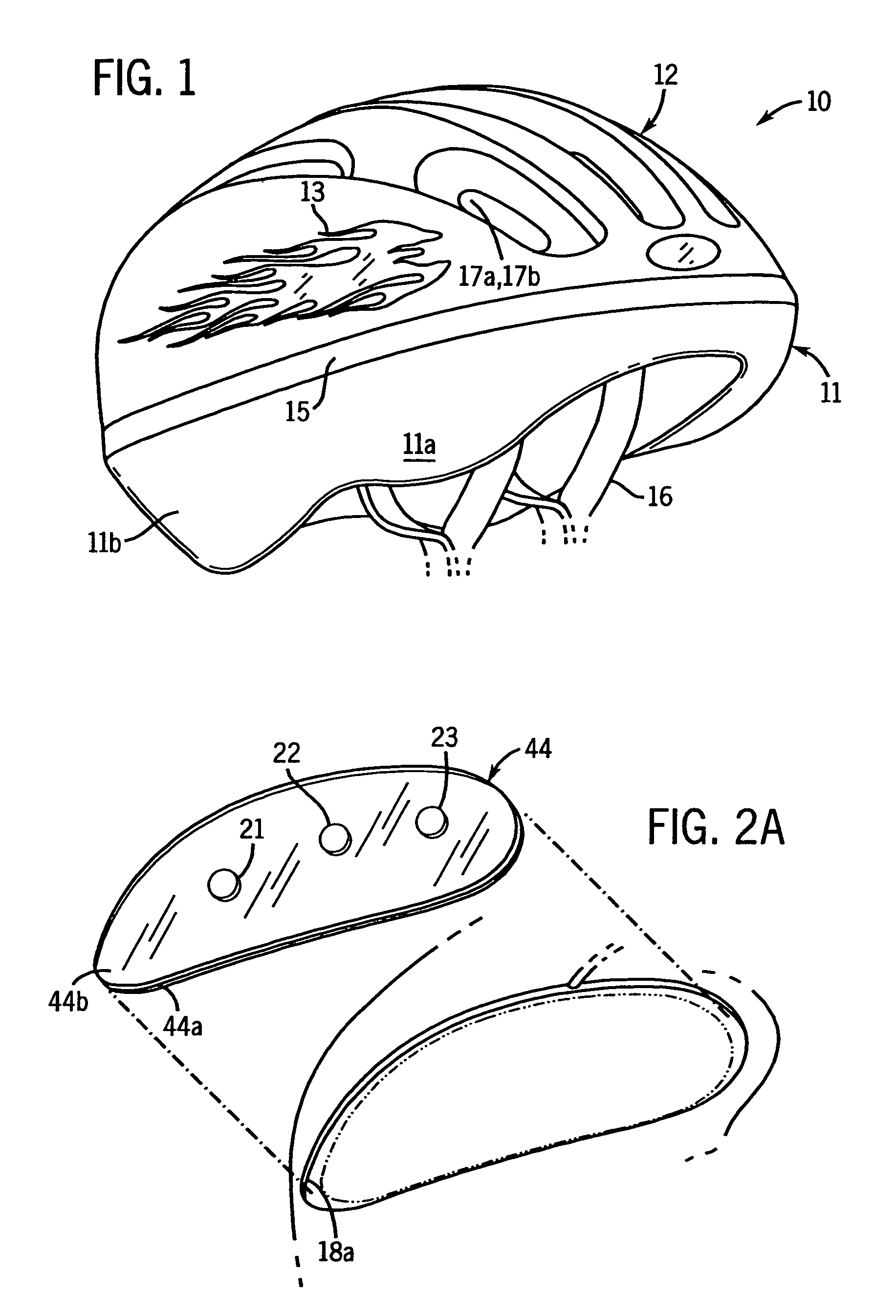
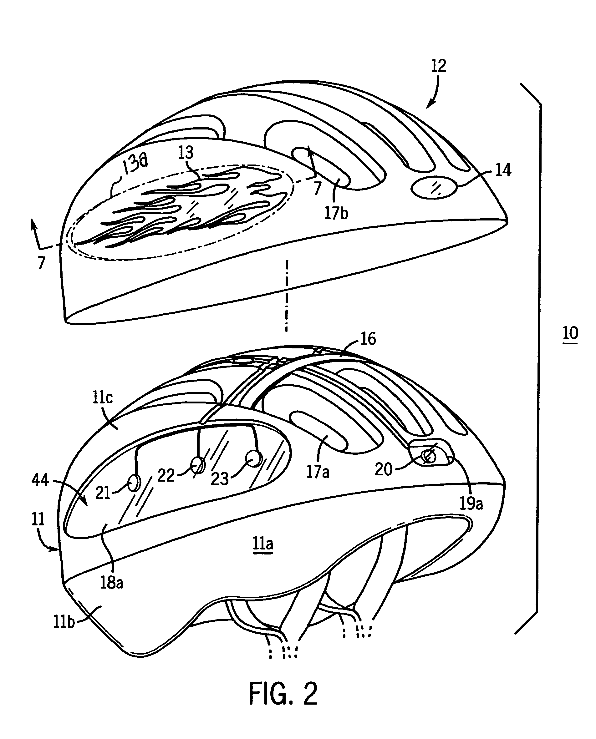
[0024]FIGS. 1–6 illustrate preferred embodiments of an illuminated protective headgear 10 of the present invention which is capable of producing the desired visual effects. The headgear 10 utilizes an inner, protective, impact-absorbing core 11 provided by molding structural polymeric foam or similar material. This core 11 has a general convex exterior surface and a general concave interior that conforms to the shape of the head of the individual. It extends in a downwardly turned fashion to provide a first ridge area 11a partly covering the sides and a second ridge area 11b extending further down the back portion of the helmet. The impact-absorbing core 11 includes any necessary padding material. Straps 16 (FIGS. 2 and 3) are threaded through slots 11d (FIG. 3) in the core 11 and fastened together at the chin of a user. Other devices currently known in the art can also be used to secure the headgear on the head of the user.

[0025]Generally, the hard outer plastic shells currently fo...


PUM


Abstract

An illuminated protective headgear (10) has an inner core (11) of resilient cushioning material with cavities (18a, 18b, 19a, 19b), an outer shell (12) with portions overlying said core (11) with windows (13) that are clear to translucent or open and are of graphical configuration disposed on opposite sides of the headgear (10), and a power circuit supported by said inner core with lighting panels (44) having light sources (21–23, 25–27, 21a–23a, 25a–27a) disposed in the cavities (18a, 18b) so as to be viewed through a respective window (13), and timing circuitry for timing the on-off sequence of the lights, so as to create an effect of motion of the illumination within each window (13). Several embodiments are disclosed.

Description

CROSS REFERENCE TO RELATED APPLICATION[0001]This is a continuation-in-part of my prior U.S. patent application Ser. No. 10 / 355,423, filed Jan. 30, 2003, now abandoned.TECHNICAL FIELD[0002]The present invention relates to an illuminated headgear of the type worn by adults and children for work-related and recreational activities.BACKGROUND ART[0003]The use of various protective headgears is growing in today's society. Protective headgears are used in many recreational activities including, but not limited to, cycling, walking, running and participation in sports activities. These activities may be carried out at night or in low light conditions such that illumination would be advantageous. For example, strips of reflective material are well known for use in jogging clothing and shoes.[0004]There have been attempts to develop illuminated headgears in industrial fields such as for mining and construction, for firefighting, and more recently for recreational use, including motorcycling....

Claims


Application Information

Patent Timeline
IPC IPC(8): F21V21/084
CPCA42B3/044Y10S362/806
Inventor KUTNYAK, MARK
Owner KUTNYAK MARK
Learn More