Eureka AIR delivers breakthrough ideas for toughest innovation challenges, trusted by R&D personnel around the world.

Shutter window/door and method

a technology for shutters and doors, applied in shutters/movable grilles, door/window protective devices, wing accessories, etc., can solve the problems of inconvenient installation, awkward or unappealing individual bolting panels, and all the panels require extra storage space, etc., to achieve the effect of convenient installation, manufacture and maintenan

Inactive Publication Date: 2006-10-17
BIGGERS DOUGLAS W
View PDF23 Cites 15 Cited by
  • Summary
  • Abstract
  • Description
  • Claims
  • Application Information

AI Technical Summary

Benefits of technology

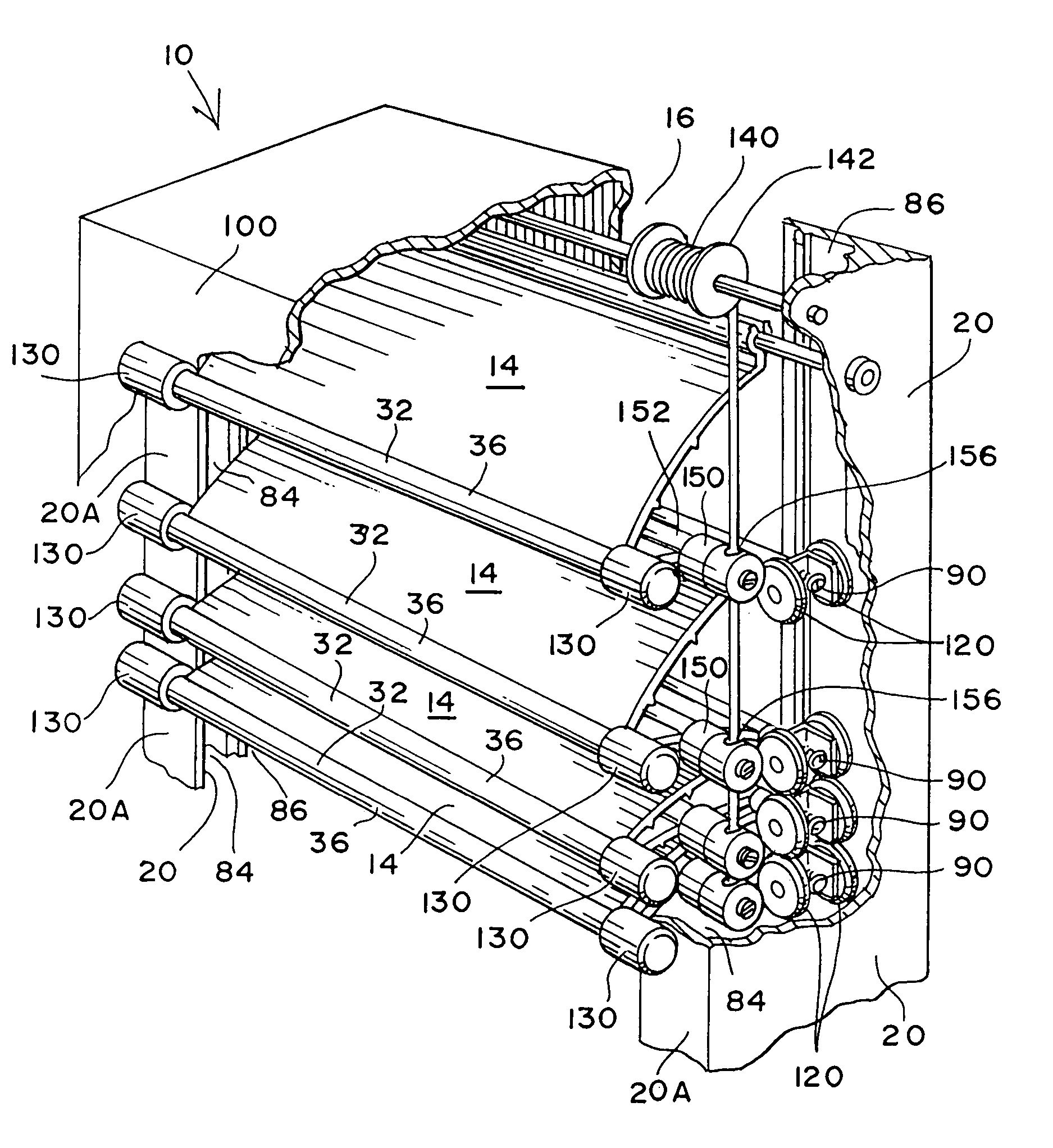
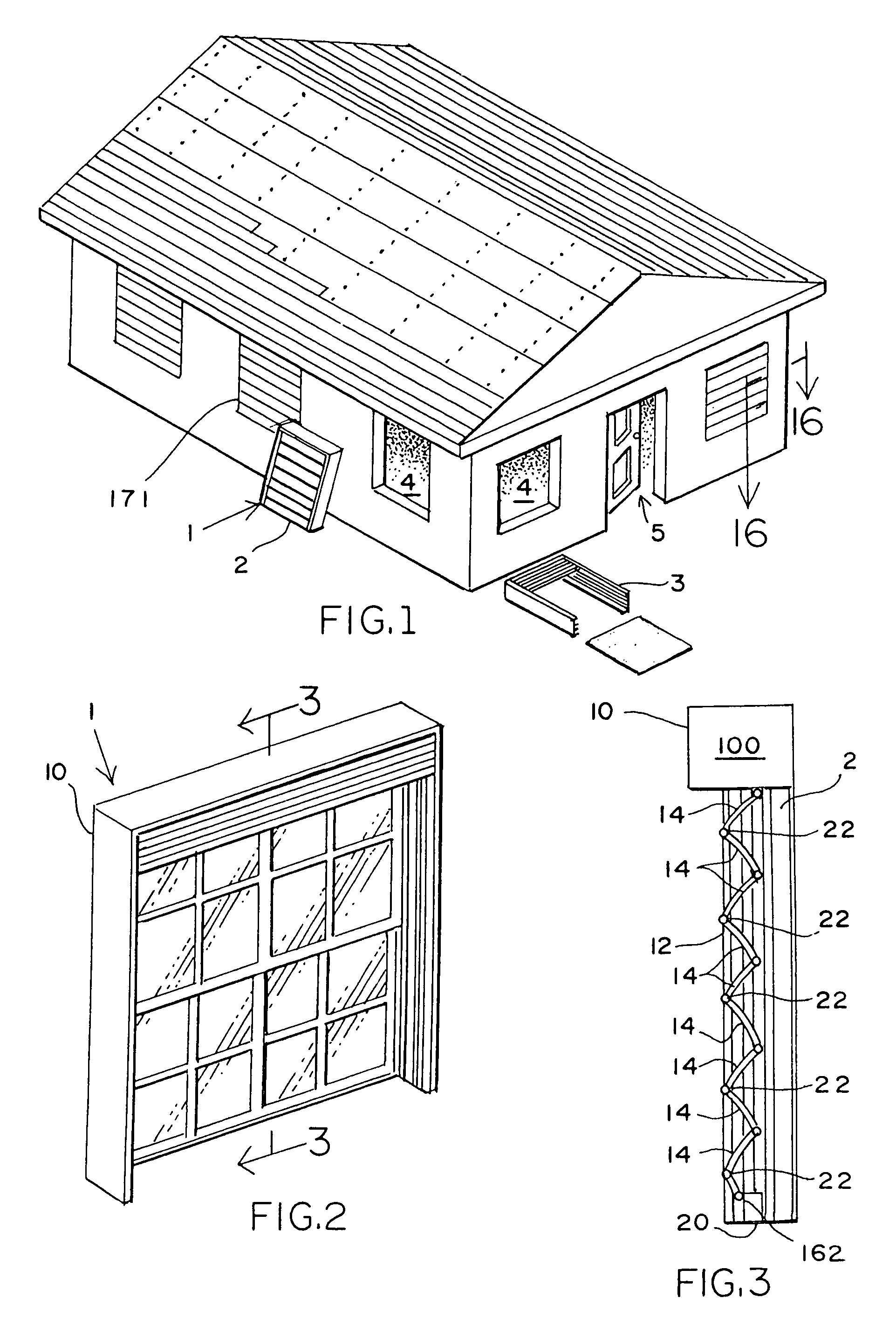
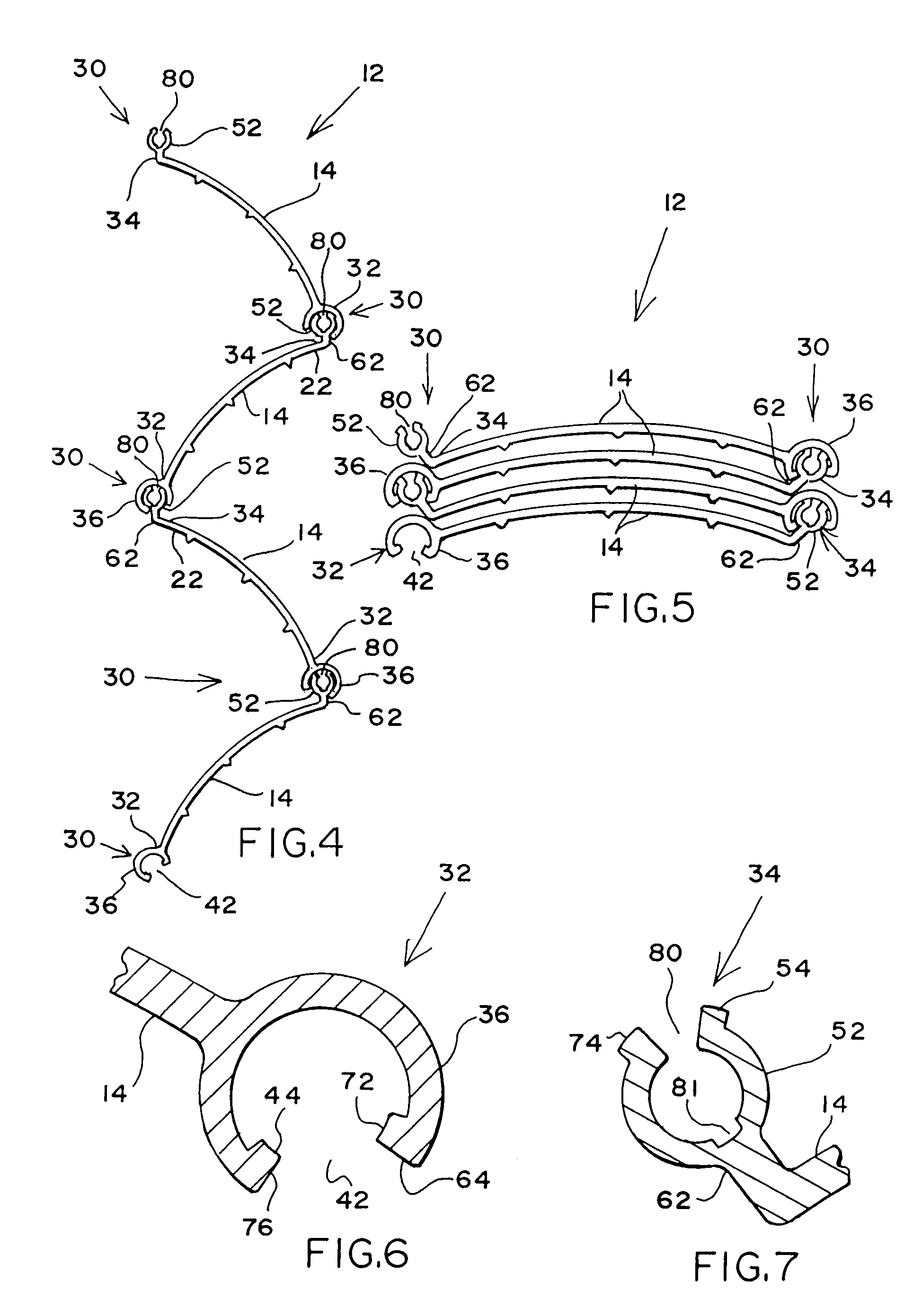
[0021]The present invention evolved from the development of a single generally rectangular frame, with extruded guides on the lateral sides, which guides contain tracks for a retractable shutter system, and similarly contain channels for the mounting of a window or a door. Important to the invention is the universality of the channels for mounting the windows or the doors so that a wide variety of commercial window or door structures may be employed with the shutter system. On the other hand, the shutter system utilizes pleated plates which are desirably formed from a single extrusion and cut to length in accordance with the dictates of the width of the opening. At the ends of the shutter panels, provision is made for a guide assembly which is secured internally of the tracks on the lateral sides of the frame. The bottom of the frame structure is left open so that the window can be inserted from the bottom, or the door can be inserted from the bottom thereby providing a cover at the top against the ingress of rain or other contaminants, while permitting drainage from the bottom. In some applications such as a beach house, the window or door may be omitted, and yet the building fitted securely with a pre-packaged frame and shutter system. Also, a plate glass picture window may be protected by the instant shutter system. In one embodiment, means are provided for removing and replacing the shutter system and shutter panels, simply and expeditiously, which does not require the removal of any cement, stucco, or any other permanent securing materials. Replacement with a different set of shutters, or even replacing single panels, and replacing the same is accomplished inexpensively and non-destructively.
[0022]A more specific aspect of the invention includes a mounting which ensures that the plates which form the shutter panel will be held in tension. A concomitant feature results from the utilization of a tension member on both sides which engages the lowest one of the plates, thereby upon lifting, no secondary jam or cross bar is required to support the weight of the plurality of plates which form the panel of the shutter.

Problems solved by technology

Some of these structures have been intended for protection against storm winds and flying debris, and yet lack sufficient strength to do the job reliably.
In addition, individually bolted panels can be awkward or unappealing because they are bulky, obstructive and conspicuous, or have too many separate parts to be economical to manufacture.
Moreover, these panels all require extra storage space off season.
A problem with Duda, if used for storm protection, is that the deployed panel presents a substantially planar composite sheet which is relatively susceptible to bending and crushing failure from object impact.
Another problem is that the locking strength of the plate edge structure is limited to the abutment of a plate face against a single opening edge in an adjacent plate.
Still another problem is that the plates forming the panels cannot be collapsed face-to-face for compact storage.
As a result, Frey and Schijf present the problems of Duda.
The plates are bowed to provide a certain degree of corrugation in the deployed panel, but there is a lack of strength at the edge joints which is similar to that described above for Duda.
Another problem is that the plates are all convex in the same direction, and thus cannot be collapsed face-to-face into a compact stack.
Kurz presents the problems identified for Duda.
A problem with Susnar is that the plates and hinge strips are separate pieces, requiring the cost of two extrusions rather than one, and the further cost of assembling the hinge strips and plates.
All of the above identified patents fail to show a working combination of a door or window in combination with an integral pre-dimensioned frame which includes a retractable shutter system of the type necessitated for hurricane protection, prevention of vandalism and burglary, and the like.

Method used


Image

  • Shutter window/door and method
  • Shutter window/door and method
  • Shutter window/door and method

Examples


first embodiment

[0033]FIG. 9 is a fragmented perspective view of an end of a panel plates showing, in exploded relation to their plate mounting positions, the guide and opening stop assemblies of the Portions of panel plates interconnected with the fragmented plate are also shown;

second embodiment

[0034]FIG. 10 is a perspective view of a building opening fitted with the inventive panel package, shown in a partially deployed position. One of the channel members is broken away to reveal the rope, spool and rope engaging assemblies at an end of every other plate in the panel;

[0035]FIG. 11 is a broken away perspective view of two interconnected plates in a deployed, corrugated position, the lower plate being pivotally connected to a window sill anchoring member with a center tubular plate channel which becomes the lifting point on the bottom elongate plate;

[0036]FIG. 12 and 13 are broken away perspective close-up views of the hinge structure first and second tubular portion of a given plate, common to both preferred embodiments;

[0037]FIG. 14 is a fragmented perspective view of an end of a panel plate, as in FIG. 9, showing in exploded relation to their plate mounting positions the fastener guide and fastener opening stop assemblies of the first and second embodiments, and the rop...


PUM


Abstract

A shutter system is disclosed which is unitized in a single rectangular frame or bracket with a window or door for use in a building opening that includes a plurality of shutter plates that can be folded and unfolded, each of the shutter plates having a hinged joint with adjoining shutter plates. The rectangular bracket has guide members with tracks for guiding the shutter plates using extensions with rollers from each of the hinged joints to cooperate with the guide members. There are also further extensions at the ends of the shutter plates on no less than every other plate, each of these securing wheel carriers at the end of the shutter plate and within a track in the rectangular bracket. The wheel carriers are equipped with a spring to put the secured shutter plate in tension because this adds additional strength to the shutter plates to resist bending and impact of the shutter system when in a fully deployed configuration.

Description

CROSS-REFERENCE TO RELATED APPLICATIONS[0001]This Application is a Continuation-In-Part of application Ser. No. 09 / 612,137, filed Jul. 7, 2000 now abandoned; which is a Continuation of application Ser. No. 08 / 902,116, filed on Jul. 25, 1997, now U.S. Pat. No. 6,148,895; which in turn is a Continuation of application Ser. No. 08 / 650,802, filed May 20, 1996, abandoned; which is a Continuation-In-Part of application Ser. No. 08 / 400,441, filed Mar. 6, 1995, abandoned; which is a Continuation of application Ser. No. 08 / 179,221, filed Jan. 10, 1994, abandoned.FIELD OF THE INVENTION[0002]The present invention relates to the construction of buildings, and more particularly closures for windows or doors. Specifically the invention relates to closures for a window or a door in which the unit is completely assembled, framed, and includes a shutter system suitable for operations in areas where hurricane resistant closures are desired.BACKGROUND OF THE INVENTION[0003]In the constructions of buil...

Claims


Application Information

Patent Timeline
Patent Type & Authority Patents(United States)
IPC IPC(8): E06B3/48E06B9/06
CPCE06B9/0638E06B9/0669
Inventor BIGGERS, DOUGLAS W.
Owner BIGGERS DOUGLAS W
Why Eureka
Eureka Blog
Learn More