
Disc drive and optical disc drive

a technology of optical discs and discs, applied in the direction of data recording, instruments, undesired vibration/sound insulation/absorption, etc., can solve the problems of inaccurate reading of information signals, optical discs cannot be loaded smoothly onto the disc table, and optical discs cannot be accurately read. to achieve the effect of accurate recording and/or reproduction

Inactive Publication Date: 2006-10-10
SONY CORP
View PDF20 Cites 13 Cited by
  • Summary
  • Abstract
  • Description
  • Claims
  • Application Information

AI Technical Summary

Benefits of technology

[0016]It is an objective of the invention to provide a disc drive and an optical disc drive that can maintain the horizontal balance of its base during operation, thereby enabling information signals to be more accurately recorded on and / or reproduced from a disc loaded therein.
[0017]It is a further objective of the invention to provide a disc drive and optical disc drive that can smoothly load and unload a disc.
[0019]It is an additional objective of the invention to provide a disc drive and optical disc drive that can be simply and easily manufactured.
[0020]Features of the invention include balanced weight distribution on a base of a disc drive and an optical disc drive, symmetrical disposition of a plurality of supporting means on the base along its center line, location-dependent provision of an elastic member with different elasticity to each of the supporting members on the base, and location-dependent provision of differential height support among the supporting means on the base.
[0021]Advantages of the invention include elimination of weight shifts / imbalance during operation of the disc drive and the optical disc drive, smooth loading / unloading of a disc, and ease of manufacture of the disc drive and the optical disc drive.

Problems solved by technology

Among others, in case the base on which the optical pickup is installed is made from a metal plate, the base will be deflected depending upon a moved position of the optical pickup and there will take place a skew with which a light beam will not be irradiated perpendicularly to a signal recording surface on the optical disc, with a result that no information signal can be read accurately.
Further, even with a little skew, no correct read of information signal can be made from an optical disc having image information, etc. recorded therein with a high density.
If the base cannot be kept horizontal in an optical disc drive in which when the base is pivoted as the disc tray is pivoted, an optical disc is loaded onto the disc table, the disc tray will collide with the disc table, so that the optical disc cannot be loaded smoothly onto the disc table.
Also in a disc drive for any disc-like recording medium other than the optical disc, if the base on which the disc rotating mechanism and write and / or read head are installed is deflected as caused by the movement of the write and / or read head and thus deformed, the write and / or read head will not be able to correctly scan a recording track on the disc-like recording medium and thus to write and / or read any information signal with good writing and reading characteristics.
However, to form a base from such a thick metal plate by pressing or the like, a large force is needed.
During production of a base from such a thick metal plate, the large pressure applied will cause a large internal stress in the metal plate.
The internal stress will make it difficult to make the base highly flat.

Method used


Image

  • Disc drive and optical disc drive
  • Disc drive and optical disc drive
  • Disc drive and optical disc drive

Examples


Embodiment Construction

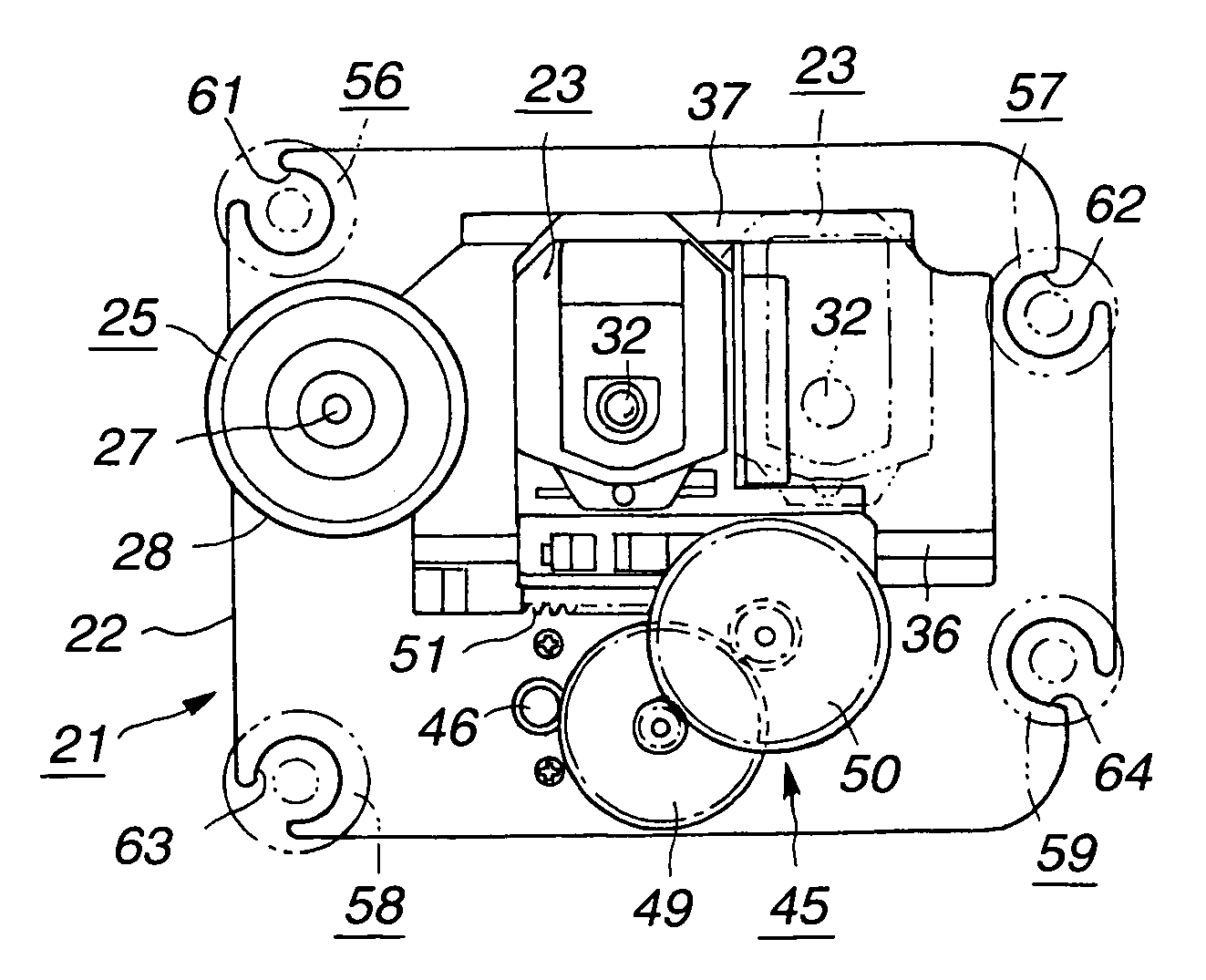
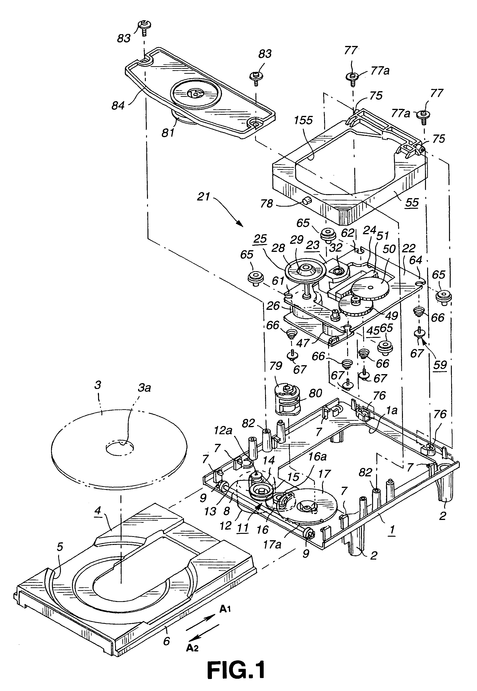
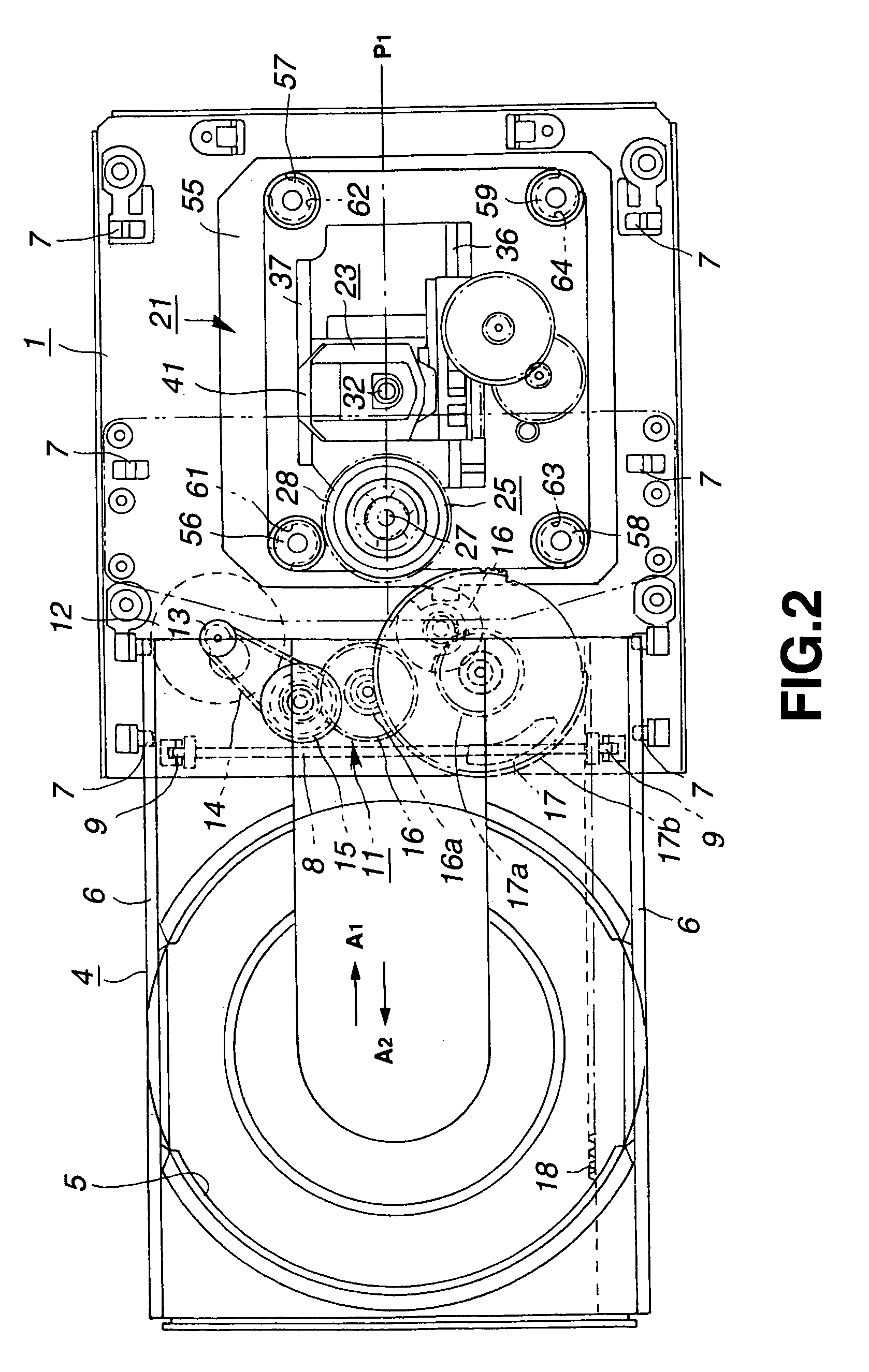
[0037]FIGS. 1 and 2 illustrate an optical disc drive according to the present invention in an exploded perspective view and a plain view, respectively. The optical disc drive includes a support pedestal 1 disposed inside a casing (not shown). The support pedestal 1 constitutes a main body of the optical disc drive, is formed by molding a synthetic resin, and has a support foot 2 disposed at each corner of the bottom thereof.

[0038]The optical disc drive also includes a disc tray 4 disposed on the support pedestal 1 for holding and carrying an optical disc 3 in and out of the support pedestal 1. The disc tray 4 contains a disc receiving concavity 5 on its upper surface for selectively position and securely hold a optical disc of two different sizes. Rails 6 are disposed along opposite sides of the disc tray 4. The support pedestal 1 has a plurality of rail supports 7 disposed along opposite sides thereof. The rails 6 of the disc tray 4 are movably supported on the rail supports 7 of t...


PUM

PropertyMeasurementUnit
thicknessaaaaaaaaaa
diameteraaaaaaaaaa
lengthaaaaaaaaaa

Abstract

An easily manufacturable optical disc drive that provides for accurate writing and reading of information signals to and from a disc loaded therein by maintaining the horizontal balance of its base during operation, and that provides for smooth loading and unloading of a disc. The optical disc drive includes a base formed of a single metal plate of 1.4–1.8 mm thickness. Major components of the base (i.e., a disc rotation driving mechanism, an optical pickup and a pickup feeding mechanism) are disposed on the base in such a way that the total weight of these components is nearly evenly distributed on the base. The optical pickup is adapted to move across an optical disc between its inner and outer circumferences, while the optical disc is rotated by the disc rotation driving mechanism. The base is supported by a plurality (i.e., at least three) of supporting members, each with an elastic support piece. These supporting members are disposed symmetrically with respect to a center line of the base along the direction of the optical pickup's movement. The symmetrical disposition of these supporting members, together with the vibration absorbing nature of the elastic support pieces and the balanced weight distribution on the base, eliminates weight shifts / imbalance caused by the optical pickup movement, thereby maintaining the horizontal balance of the base at all time during operation of the optical disc drive. The ease of manufacture can be achieved by selecting even numbers (e.g., four) of the supporting members for the base.

Description

BACKGROUND OF THE INVENTION[0001]1. Field of the Invention[0002]The present invention relates to disc drives and optical disc drives, and in particular, to disc drives and optical disc drives for loading and unloading discs and for writing and reading information signal to and from such discs.[0003]2. Description of the Related Art[0004]Conventionally, a disc drive is used in which a disc-like recording medium such as an optical disc, magneto-optical disc or magnetic disc is used as the recording medium.[0005]The disc drives of this type include an optical disc drive in which an optical disc is used as the recording medium. In the optical disc drive, there are installed on a common base a disc rotation driver to drive the rotation of an optical disc and an optical pickup to scan, by a light beam, a signal recording area on the optical disc being rotated by the disc rotation driver, thereby reading an information signal recorded in the optical disc.[0006]The base is formed from a thi...

Claims


Application Information

Patent Timeline
Patent Type & Authority Patents(United States)
IPC IPC(8): G11B7/08G11B17/00G11B17/02G11B33/12G11B17/04G11B33/00G11B33/08H05K7/14
CPCG11B7/08G11B7/082G11B17/05G11B17/056G11B17/02
Inventor MAEDA, TETSUO
Owner SONY CORP
Learn More