Image forming apparatus and control method for rotating image data based on sheet type and orientation

a technology of image data and forming apparatus, which is applied in the direction of digital output to print units, instruments, electrographic processes, etc., can solve the problems of preventing the intended output results of users, unable to obtain desired output images, and unable to achieve desired output images

Active Publication Date: 2006-10-10
CANON KK
View PDF6 Cites 8 Cited by
  • Summary
  • Abstract
  • Description
  • Claims
  • Application Information

AI Technical Summary

Benefits of technology

[0014]It is a specific object of the present invention to provide an image forming apparatus, a control method therefor, a method for controlling the output of image data which can obtain proper output results ...

Problems solved by technology

Consequently, the user's intended output results may not be obtained.
The above-mentioned operations, however, are very cumbersome to the user, and when the user himself must perform such cumbersome operations, he is likely to make a mistake in setting the sheets or operating the apparatus, thus failing to obtain desired output images.
For example, with an image forming apparatus having a punching pr...

Method used


Image

  • Image forming apparatus and control method for rotating image data based on sheet type and orientation
  • Image forming apparatus and control method for rotating image data based on sheet type and orientation
  • Image forming apparatus and control method for rotating image data based on sheet type and orientation

Examples


first embodiment

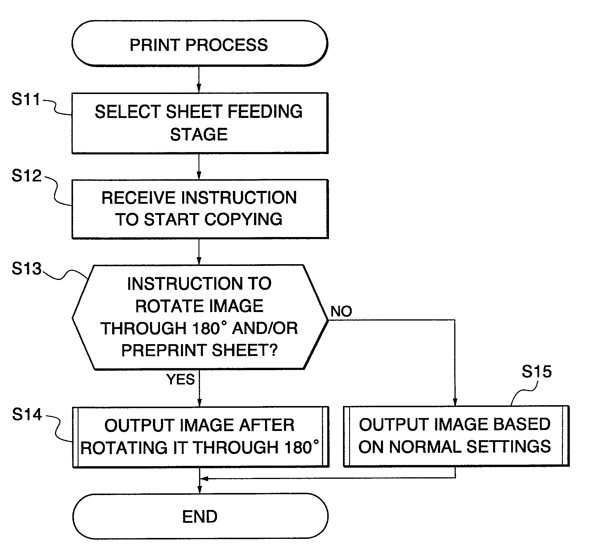
[0116]As described above, in this first embodiment, when an image is output to a directional recording sheet such as the preprint sheet, the loaded image is rotated through 180° to obtain an image output in which the direction of a previously printed image corresponds to the direction of the newly printed image.

[0117]FIG. 11 is a flow chart showing a manner of controlling the output of image data according to a second embodiment of the present invention. In the second embodiment, image data are printed on a sheet (hereinafter referred to as “the prepunched sheet”) previously subjected to a punching process.

[0118]First, the user sets prepunched sheets in the sheet feeding section 45, for example, the first sheet feeding cassettes 45a, selects a “prepunched sheet” button (indicated by symbol B in FIG. 7) displayed on the liquid crystal panel in FIG. 7, and then selects a sheet feeding stage (step S11) and gives an instruction to start copying (step S12) in the same manner as in the fi...

second embodiment

[0121]As described above, in this second embodiment, since the prepunched sheet has been already subjected to the prepunching process, a sheet working process such as the punching process (including the staple process) is inhibited from being executed on this prepunched sheet (for example, the function button displayed on the operating section and corresponding to this sheet working process is disabled). Alternatively, for example, the operation of the punch unit or the stapler is inhibited because the image forming apparatus of the present embodiment can be connected to (or may be incorporated in) a sheet processing unit that can execute a sheet working process such as the one described above). Further, since this prepunched sheet is directional due to the presence of the punch holes, in order to avoid an improper relationship between the punch holes (that is, the binding position) on the prepunched sheet and the location of the input image as in the prior art, the direction in whi...


PUM


Abstract

To obtain proper output results regardless of the type of recording sheets and obtain the user's desired output results without having the user perform cumbersome operations, the user operates an operating section to select a sheet feeding stage, gives an instruction to start copying, and then a controller section 15 of an image forming apparatus determines whether or not a 180° rotation mode for rotating image data through 180° is set and/or whether or not preprint sheets are used for recording. If the answer is negative, the image data are output based on normal settings. On the other hand, if the answer is affirmative, the image data are output after being rotated through 180°.

Description

BACKGROUND OF THE INVENTION[0001]1. Field of the Invention[0002]The present invention relates to an image forming apparatus for forming images on sheets, a control method therefor, an image data output control method, and storage media storing programs for executing these methods.[0003]2. Description of the Related Art[0004]Conventional image forming apparatuses such as digital copiers output image data read by a scanner or the like, without changing the direction of the image data so that the output results are rotated through 180° as viewed from a user. This allows fast image processing but necessitates controlling of process positions in performing a punching process, a stapling process, and the like associated with the image processing.[0005]FIGS. 14A to 14D are views showing how an image is processed starting with scanning of the original on an original table and ending with outputting of the image onto a recording sheet.[0006]If an original with a character “” depicted thereon...

Claims


Application Information

Patent Timeline
IPC IPC(8): B41B23/00B41J21/00B41J2/44G03G15/36G03G21/00G06F3/12G06T3/60H04N1/00H04N1/23H04N1/387H04N1/60
CPCH04N1/2307H04N1/2323H04N1/2353H04N1/3247H04N1/6097
Inventor SHIMIZU, YASUSHIASAI, HIDEHIKOKASAI, KAZUHIRO
Owner CANON KK
Why Eureka
Try Eureka