Combination bucket/breaker apparatus for excavator boom stick

a technology of excavators and buckets, applied in mining devices, mining structures, constructions, etc., can solve the problems of increasing the total substantially increasing the cost of a given excavation task, and undesirably increasing both the manpower and equipment cost of a given excavation project, so as to increase avoid operation. , the effect of increasing the efficiency of the excavation process

Inactive Publication Date: 2006-10-10
UNDERWOOD LOWELL A
View PDF13 Cites 4 Cited by
  • Summary
  • Abstract
  • Description
  • Claims
  • Application Information

AI Technical Summary

Benefits of technology

[0017]Another advantage of the present invention is that the bucket can be operated without fully stowing the breaker. Likewise, the breaker may be operated without the necessity to fully extend the bucket. This increases the efficiency of the excavation process by providing immediate access to each of the tools, without delay. Another advantage of this capability is that it further increases the efficiency of the excavation process by rendering the bucket available to frequently scrape away the freshly generated cuttings so the breaker tool is always exposed to fresh refusal material, avoiding operation against previously generated cuttings. Another advantage of this capability is that by avoiding operation against previously generated cuttings, the breaker tool will last longer.
[0018]In an illustrated preferred embodiment thereof, the excavating machine is also provided with control circuitry coupled to the drive apparatus and useable to operate it. Representatively, the control circuitry includes a hydraulic flow circuit in which the drive apparatus is interposed; a flow controller operative to electively reverse the direction of hydraulic fluid flow through a portion of the hydraulic flow circuit; a diverting valve apparatus interconnected in the hydraulic flow circuit and operable to selectively route hydraulic fluid through the hydraulic flow circuit to (1) a first portion of the drive apparatus associated with the bucket, or (2) a second portion of the drive apparatus associated with the breaker; and a switch structure useable to selectively operate the diverting valve apparatus.
[0019]In another illustrated preferred embodiment of the present invention, a breaker and deployment system is disclosed, having a mounting bracket attached to the underside and lower end of the boom stick. A breaker is pivotally attached to a first pivot on the bracket. In the preferred embodiment, the first pivot is bifurcated. A hydraulic cylinder is pivotally attached at a second pivot on the bracket, in close proximity to the first pivot. The hydraulic cylinder is pivotally attached to the breaker at a third pivot. This embodiment has the advantage of requiring only one hydraulic cylinder. This embodiment has the additional advantage of using a much shorter hydraulic cylinder. This embodiment has the additional advantage of rapid deployment and retraction of the breaker. This embodiment has the additional advantage of a more stable and durable assembly during use. This embodiment has the additional advantage of being much easier and faster to install or remove. This embodiment has the additional advantages of being less expensive to manufacture, install, and service. This embodiment has the additional advantage of resulting in an increased range of motion of the deployed tool. This embodiment has the additional advantage of providing protection for the hydraulic cylinder when the tool is deployed and operational. This embodiment has the additional advantage of resulting in a less obstructive configuration of the hydraulic cylinder in relation to the boom stick when deployed.
[0020]In another illustrated preferred embodiment of the present invention, a bracket is attached to the inside and lower end of the boom stick. A breaker is pivotally attached to a first pivot on the bracket. A latch-lock assembly is mounted to, and between, the boom stick and the breaker. This embodiment has the advantage of preventing undesired, partial deployment of the breaker from the vibration and impact forces encountered during operation of the bucket. In a preferred embodiment, the latch-lock assembly comprises a slide latch located in a guide box attached to the boom stick for latching engagement with a strike attached to the breaker assembly. In another preferred embodiment, the latch-lock assembly comprises a ball latch attached to the boom stick for latching engagement with a strike ball attached to the breaker assembly.
[0021]In another illustrated preferred embodiment of the present invention, a shock absorbing retraction stop is attached to the boom stick. This prevents damage to the breaker and the boom stick when the breaker is in the stowed position, encountering vibration and impact forces during operation of the bucket.
[0022]In another illustrated preferred embodiment of the present invention, a bracket is attached to the underside and lower end of the boom stick. A breaker is pivotally attached to a first pivot on the bracket. Deployment of the breaker is made by the force of gravity acting on the breaker, upon release of the latch-lock assembly. In this embodiment, a controllable hydraulic cylinder is unnecessary to forcibly move the breaker. The breaker may be stowed by retracting the bucket into the breaker, thus forcing it upwards and against the boom stick until the latch-lock assembly can be engaged to secure the breaker in place. This embodiment has the advantage of being easily retrofit onto excavating machines without modification of the hydraulic system. An additional advantage of this embodiment is the lower cost of materials and installation. Optional to this embodiment, an uncontrolled hydraulic or pneumatic cylinder may be used to prevent free fall of the breaker upon release of the latch-lock. An advantage of this embodiment is increased safety.

Problems solved by technology

While this procedure is easy to describe, it is a difficult, laborious and time-consuming task for the operator to actually carry out due to the great size and weight of both the bucket and breaker which must be attached to and then removed from the stick, and the necessity for the operator to climb into and out of the high cab area of the excavator (often in inclement weather) to effect each bucket and breaker changeout on the stick.
While this digging / breaking technique is easier on the operator, it is necessary to dedicate two large and costly excavators to a given digging task, thereby substantially increasing the total cost of a given excavation task.
This, of course, undesirably increases both the manpower and equipment cost for a given excavation project.
A primary disadvantage of these devices is complexity, cost, and reliability.
Another disadvantage is the weight that must be continuously carried by the bucket.
The additional weight substantially reduces the carrying capacity and mobility of the bucket.
Another disadvantage to the device of U.S. Pat. No. 6,085,446 is that the back of the bucket cannot be used to smooth or pad the soil, as is a well-known practice in the industry.
Another disadvantage is that surface rock is not subject to an overburden pressure, so it generally fails faster under compression and impact forces than by the shearing forces of a scrapping and gouging rotary drilling tool.
A primary disadvantage of this device is that it is extremely complex and expensive.
Another disadvantage of this device is that it cannot be retrofit to existing excavators.
Another disadvantage of this device is that the size of the breaker is limited.
Another disadvantage of this device is that the bucket must be fully stowed to access the breaker and vice versa, making simultaneous operation impractical.
A primary disadvantage of this device is that it fails to permit immediate, unassisted switching from breaker to bucket, and thus simultaneous operation is impossible.
Another disadvantage of this device is that it requires manual handling of the extremely heavy chisel tool each time the operator desires to convert to a breaker or bucket operation.
Another disadvantage of this device is that it is extremely complex and expensive.
Another disadvantage of this device is that it cannot be retrofit to existing excavators.

Method used


Image

  • Combination bucket/breaker apparatus for excavator boom stick
  • Combination bucket/breaker apparatus for excavator boom stick
  • Combination bucket/breaker apparatus for excavator boom stick

Examples


Embodiment Construction

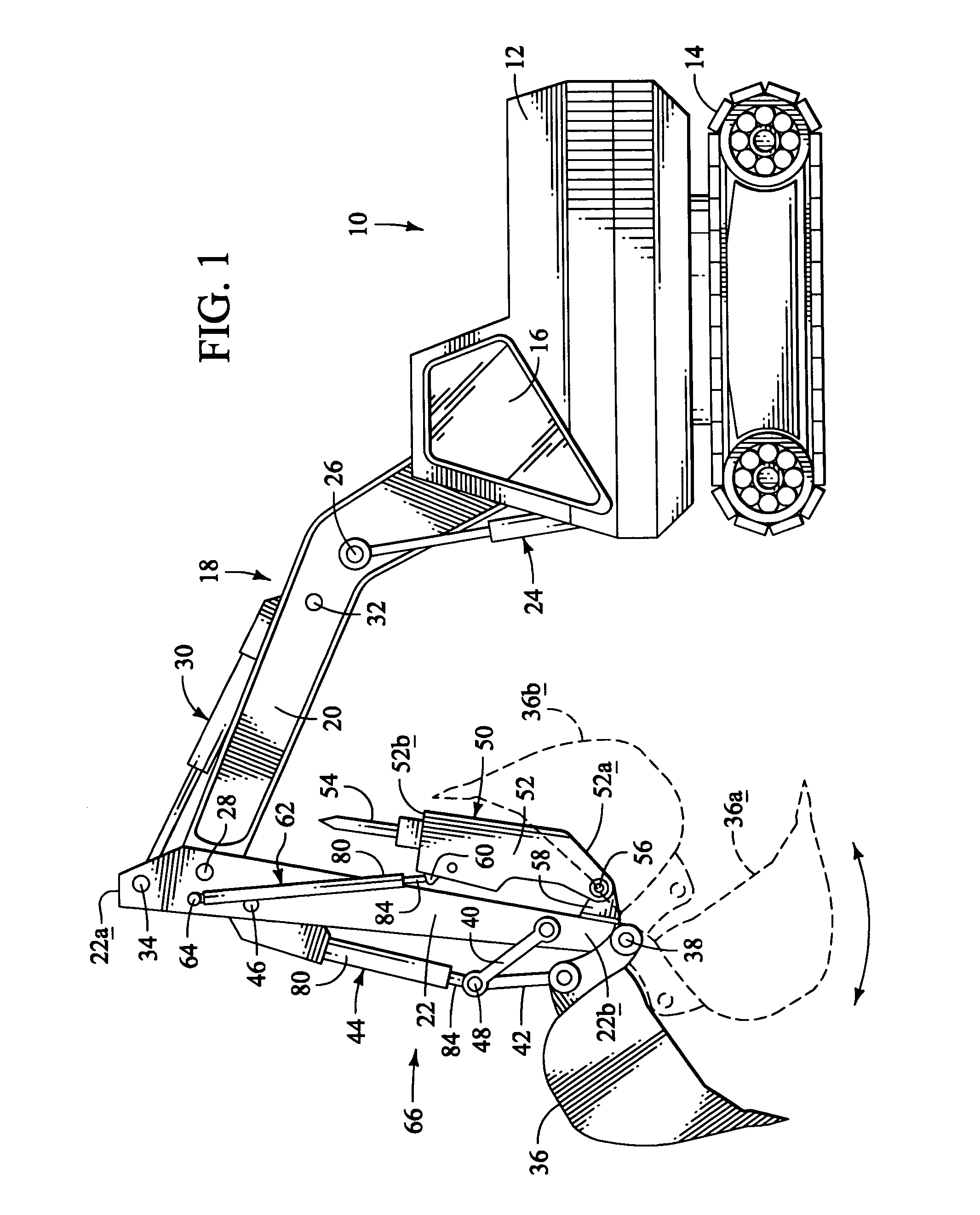
[0049]Illustrated in simplified form in FIGS. 1 and 2 is an earth excavating machine which is representatively in the form of a tracked excavator 10 having a body portion 12 supported atop a wheeled drive track section 14 and having an operator cab area 16 at its front or left end. While a tracked excavator has been illustrated, it will be readily appreciated by those of skill in this particular art that the principles of the present invention, as later described herein, are equally applicable to other types of earth excavating machines including, but not limited to, a wheeled excavator and a rubber-tired backhoe. It is further understood that the invention may assume various orientations and step sequences, except where expressly specified to the contrary. It is also to be understood that the specific devices and processes illustrated in the attached drawings, and described in the following specification are simply exemplary embodiments of the inventive concepts defined in appended...


PUM


Abstract

An excavating machine, representatively a tracked excavator has a boom stick portion on which both an excavating bucket and a hydraulic breaker are mounted for hydraulically driven pivotal movement between first and second limit positions. The bucket may be operated independently of the breaker for digging operations. Similarly, the breaker may be operated independently of the bucket for refusal material-breaking operations. The same excavating machine may now use the bucket and breaker in a rapid and continuous exchange to permit frequent removal of small quantities of broken refuse material with the bucket, exposing the bucket and breaker to fresh refuse material. A lubricatable attachment system is disclosed for improved breaker system connectivity that permits quick installation and removal of the breaker. An alternative deployment system is disclosed having a rotary actuator for efficient and rapid deployment without the need for an additional hydraulic cylinder.

Description

CROSS REFERENCE TO RELATED APPLICATION[0001]This application is a Continuation-in-part of U.S. application Ser. No. 10 / 150,057 filed May 17, 2002, now U.S. Pat. No. 6,751,896, which is a Continuation-in-part of U.S. application Ser. No. 09 / 624,099 filed Jul. 24, 2000, now U.S. Pat. No. 6,430,849.BACKGROUND OF THE INVENTION[0002]1. Technical Field[0003]The present invention generally relates to a material handling apparatus and, in a preferred embodiment thereof, more particularly relates to an excavating apparatus, representatively a tracked excavator, having operatively attached to the stick portion of its boom a specially designed combination bucket and breaker structure which uniquely permits the excavator operator to selectively carry out either digging or refusal material breaking tasks without having to change out equipment on the stick.[0004]2. Description of Related Art[0005]Large scale earth excavation operations are typically performed using a powered excavating apparatus,...

Claims


Application Information

Patent Timeline
Patent Type & Authority Patents(United States)
IPC IPC(8): E02F3/96
CPCE02F3/964E02F3/966Y10S37/903
Inventor UNDERWOOD, LOWELL A
Owner UNDERWOOD LOWELL A
Why Eureka
Try Eureka