
Phase-switched dual-mode counter circuit for a frequency synthesizer

a counter circuit and frequency synthesizer technology, applied in the direction of pulse automatic control, modulation, pulse technique, etc., can solve the problems of power consumption, logic part of the circuit slowing down the whole circuit, and more difficult design than simple fixed division ratio frequency dividers, etc., to achieve the effect of facilitating implementation

Inactive Publication Date: 2006-10-03
THE SWATCH GRP RES & DEVELONMENT LTD
View PDF8 Cites 5 Cited by
  • Summary
  • Abstract
  • Description
  • Claims
  • Application Information

AI Technical Summary

Benefits of technology

[0019]Thus a main object of the invention is to alleviate the drawbacks of the prior art by providing a high-speed dual-modulus prescaler circuit with means in particular for avoiding inopportune voltage drops when switching phase.
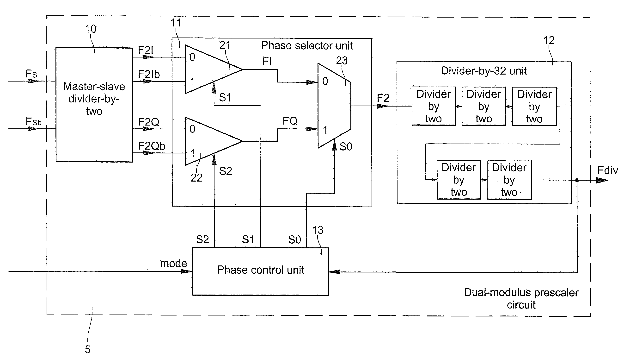
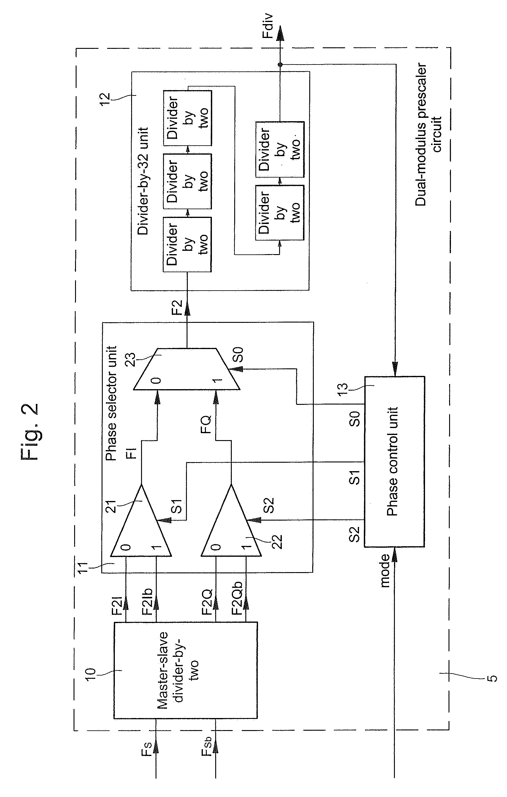
[0021]One advantage of the dual-modulus prescaler circuit of the invention is that it is independent of the frequency of the high-frequency signals applied to the input of the circuit. Thanks to phase switching between a first signal and a second signal in a phase lead of 90° in relation to the first signal, no voltage drop occurs in the output signal of the selector unit. Because of this, it is not necessary to slow down the beginning and / or the slope of control signal transition.
[0024]Another advantage of the dual-modulus prescaler circuit of the invention is that the control unit is clocked synchronously by a clock signal corresponding to the output signal of the last divider-by-two of the chain of dividers. That clock signal is therefore never interrupted to clock operations in the control unit. Moreover, the control signals produced by said control unit are free of disturbances and / or delays.
[0026]Note that the use of dividers-by-two, especially asynchronous dividers, in the divider chain facilitates the implementation of said high-speed dual-modulus prescaler circuit.

Problems solved by technology

Several embodiments of dual-modulus type prescaler circuits have already been proposed, but since these circuits have to operate at high speed, they are more difficult to design than simple fixed division ratio frequency dividers.
One problem is that, in achieving frequency division using first and second division factors, the logic part of the circuit slows down the whole of the circuit.
As a result, the flip-flops in the synchronous divider unit operate at a high frequency, which may be a disadvantage from the power consumption point of view in particular.
Another disadvantage of this type of circuit is that fine adjustment of frequency division by the two division factors is not possible, in particular because a first divider-by-two is used to reduce the frequency of the high-frequency signal.
It is therefore not possible to provide frequency divisions by division factors having a smaller difference between them.
A major drawback of the solution described in the article by Mrs.
On the other hand, if the frequency of said high-frequency signals is not sufficiently high, voltage drops occur in the output signal at the time of phase switching.
It may prove difficult to adjust the beginning and / or the slope of the transitions in the control signals to take account of the frequency of the high-frequency signals received that is to be divided.
Jan Craninckx and Michiel S. J. Steyaert is not normally able to divide signals whose frequency is relatively low.
Moreover, the problem of voltage drops is also dependent on the supply voltage of the dual-modulus prescaler circuit.

Method used


Image

  • Phase-switched dual-mode counter circuit for a frequency synthesizer
  • Phase-switched dual-mode counter circuit for a frequency synthesizer
  • Phase-switched dual-mode counter circuit for a frequency synthesizer

Examples


Embodiment Construction

[0034]Note that, because they are well known to the person skilled in the art, the components of the dual-modulus prescaler or divider counter circuit are not described in detail in the following description.

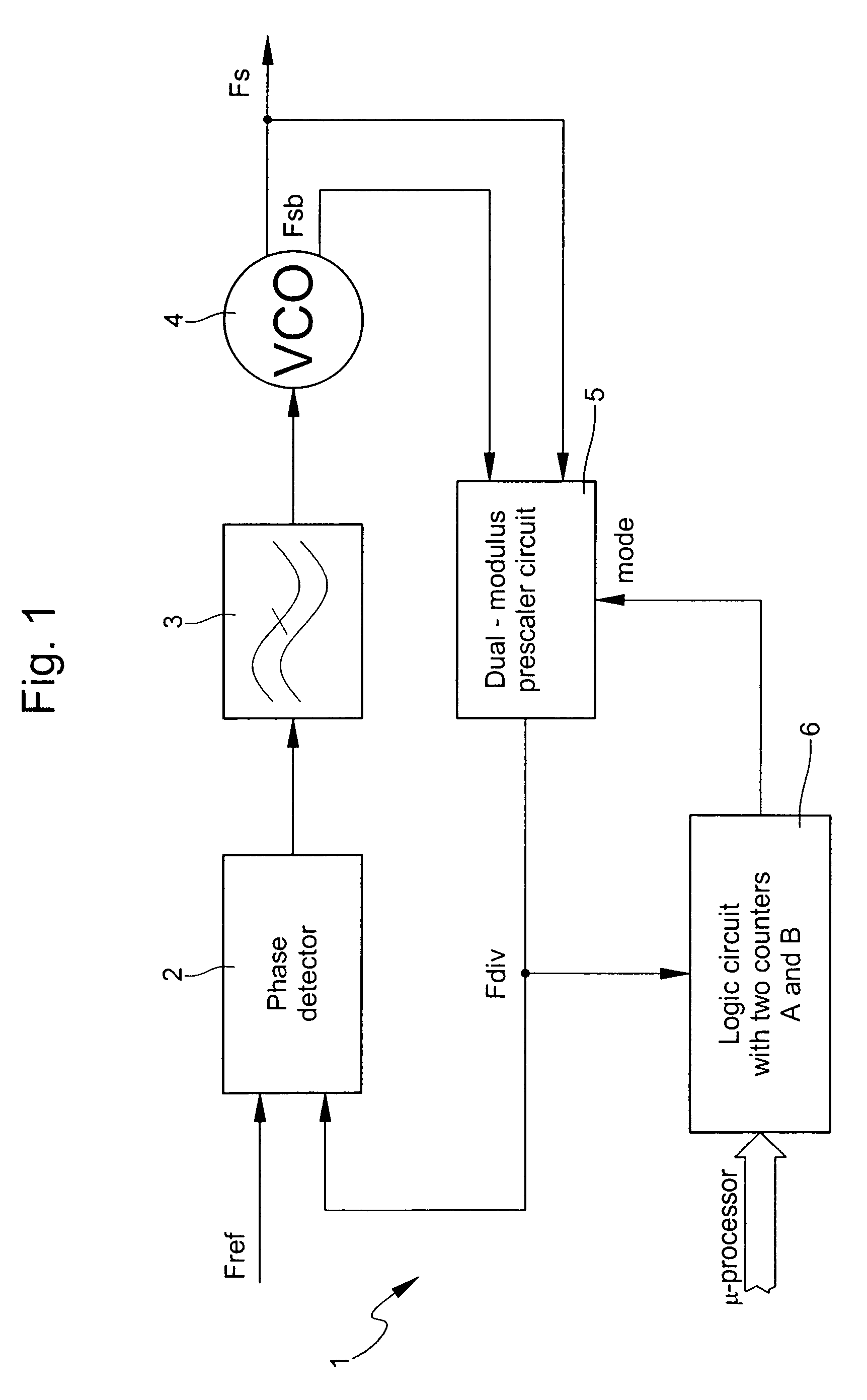
[0035]As described hereinabove with reference to FIG. 1, the dual-modulus prescaler circuit is used in a control loop of a frequency synthesizer. The synthesizer may be used in radio-frequency signal transmitters and / or receivers used in small portable devices for short-range wireless communications, for example. The frequency of radio-frequency signals for short-range wireless communications is close to 0.5 GHz, for example 434 MHz. As a general rule, the synthesizer supplies high-frequency signals for demodulating radio-frequency signals. The synthesizer may be designed for incorporation into a wristwatch, for example, which contains a small accumulator or battery. The dual-modulus prescaler circuit must in particular consume little current during periods in which the synthesi...


PUM


Abstract

A dual-modulus prescaler circuit for a frequency synthesizer comprises a plurality of asynchronous dividers-by-two connected in series, a phase selector unit (11) between two dividers-by-two (10, 12) and a control unit (13) for supplying control signals (S0, S1, S2) to the selector unit as a function of a selected mode. Said selector unit receives four signals phase shifted by 90° in relation to each other from a master-slave first divider and supplies a selected one of the four phase shifted signals. The control signals (S0, S1, S2) are supplied to the selector unit for selecting one of the four phase shifted signals (F2) at the output in a particular division period. As a function of the control signals supplied by the control unit (13) in one selected of the modes, the selector unit effects phase switching in each division period between two phase shifted signals selected by each branch. The second phase shifted signal i in phase lead of 90° in relation to the first phase shifted signal.

Description

BACKGROUND OF THE INVENTION[0001]The invention relates to a switched phase dual-modulus prescaler or divider counter circuit for a frequency synthesizer. The circuit divides the frequency of at least one high-frequency signal by a first factor in a first selected mode and by a second factor in a second selected mode. It comprises a plurality of asynchronous dividers-by-two connected in series. One of the dividers-by-two is of the master-slave type for receiving two input signals in phase opposition, and for supplying four signals phase shifted by 90° in relation to each other. The circuit further comprises a phase selector unit inserted between two of the dividers-by-two for receiving the four phase shifted signals from the master-slave first divider and for supplying a selected one of the four phase shifted signals to the second divider. A control unit supplies control signals to the phase selector unit for selecting a phase shifted signal.[0002]Frequency synthesizers are used to s...

Claims


Application Information

Patent Timeline
IPC IPC(8): H03K21/00H03K23/66H03L7/081H03L7/18H03L7/197
CPCH03K23/667H03L7/081H03L7/18H03L7/1974H03L7/197
Inventor CASAGRANDE, ARNAUD
Owner THE SWATCH GRP RES & DEVELONMENT LTD
Learn More