
Hinge device for a flat panel display

a flat panel display and hinge device technology, applied in the direction of wing accessories, details of portable computers, instruments, etc., can solve the problems of increased production cost of hinge devices, reduced friction between display panels and pedestal bases of notebook computers, and reduced friction between display panels and pedestal bases, etc., to achieve simplified structure, increase surface contact area, and increase frictional contact area

Inactive Publication Date: 2006-10-03
JIIN MING IND
View PDF14 Cites 27 Cited by
  • Summary
  • Abstract
  • Description
  • Claims
  • Application Information

AI Technical Summary

Benefits of technology

"The present invention provides a hinge device for a flat panel display that allows for easy adjustment of the display panel to a desired angle. The hinge device includes a fixed unit with spindle bores and bushings with annular ribs, and a pivotal unit with pivotal bearing portions and separating bearing blocks. The bearing blocks have annular grooves that clamp around the bushing. The hinge device is made of plastic or metal and has a simplified structure and reduced production cost. The technical effects of the invention are increased friction between the pivotal and fixed units, making the pivoting and positioning more stable and reliable, and a simplified structure and reduced production cost."

Problems solved by technology

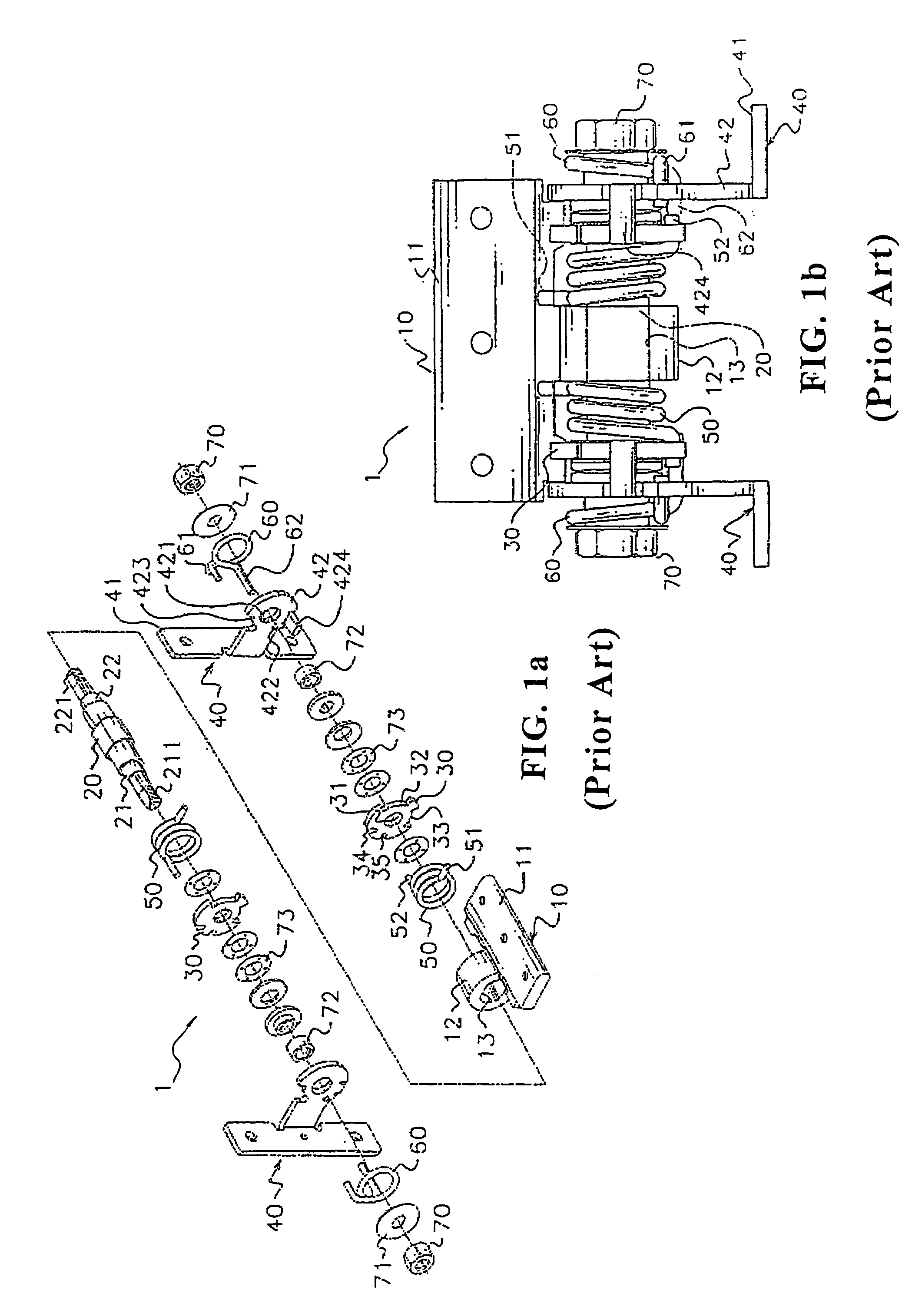
However, it can be understand that the friction between the display panel and the pedestal base of the Notebook (NB) computer tends to be reduced after having been used for a long time, and external contacting surface of the metal-made spindle and corresponding internal contacting surface of the plastic sleeve may be grinded, whereby the positioning of the display panel may lose balance.
However, the structure of the above described hinge device of the prior art is complicated with too many parts and accessories, i.e. the production cost of the hinge device is increased, and the possibility of trouble is also increased so that the technological level / cost is high.

Method used


Image

  • Hinge device for a flat panel display
  • Hinge device for a flat panel display
  • Hinge device for a flat panel display

Examples


Embodiment Construction

[0025]The technical features of the present invention will be described further with reference to the embodiments. The embodiments are only preferable examples without limiting to the present invention. It will be well understood by the following detail description in conjunction with the accompanying drawings.

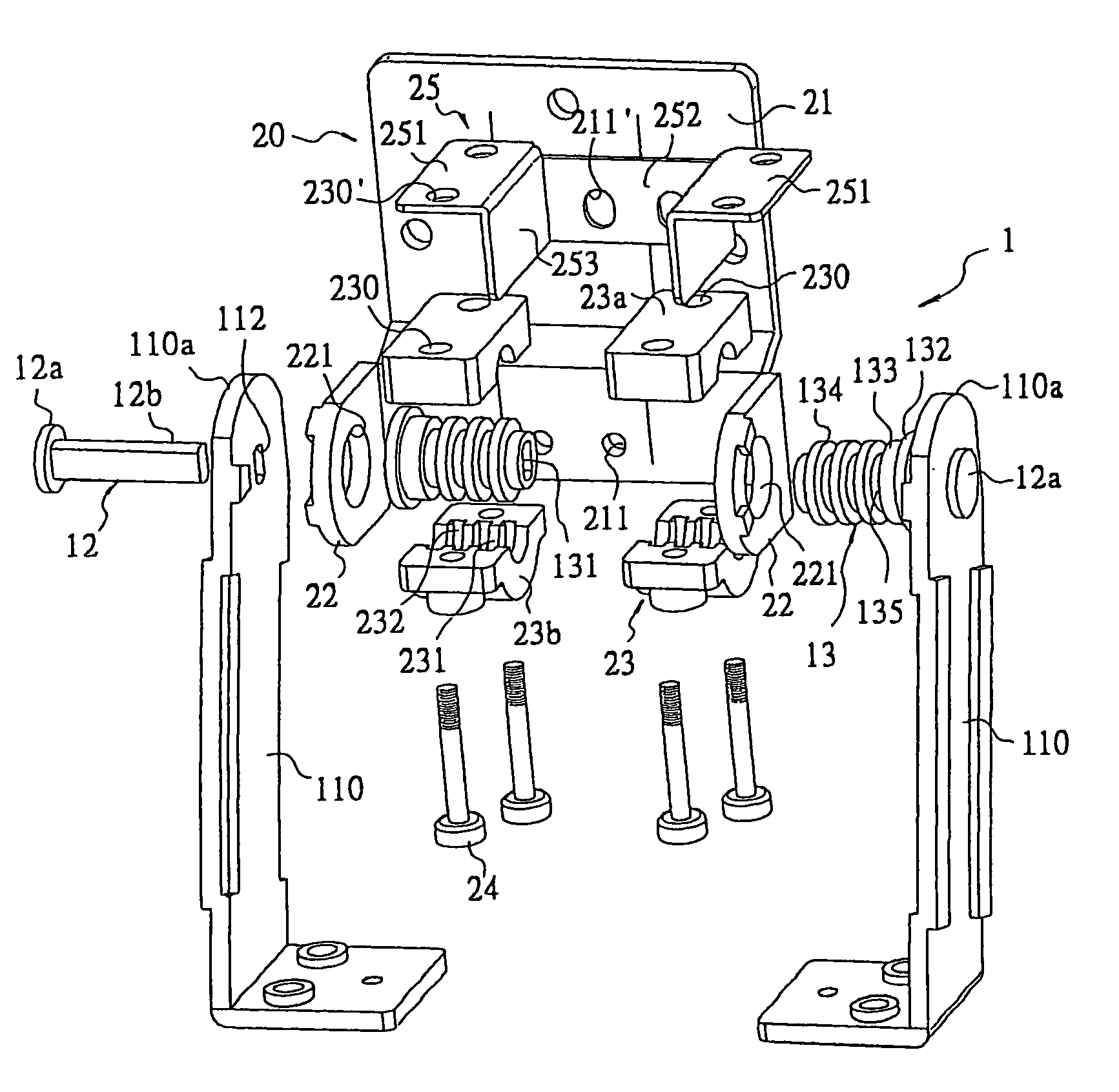
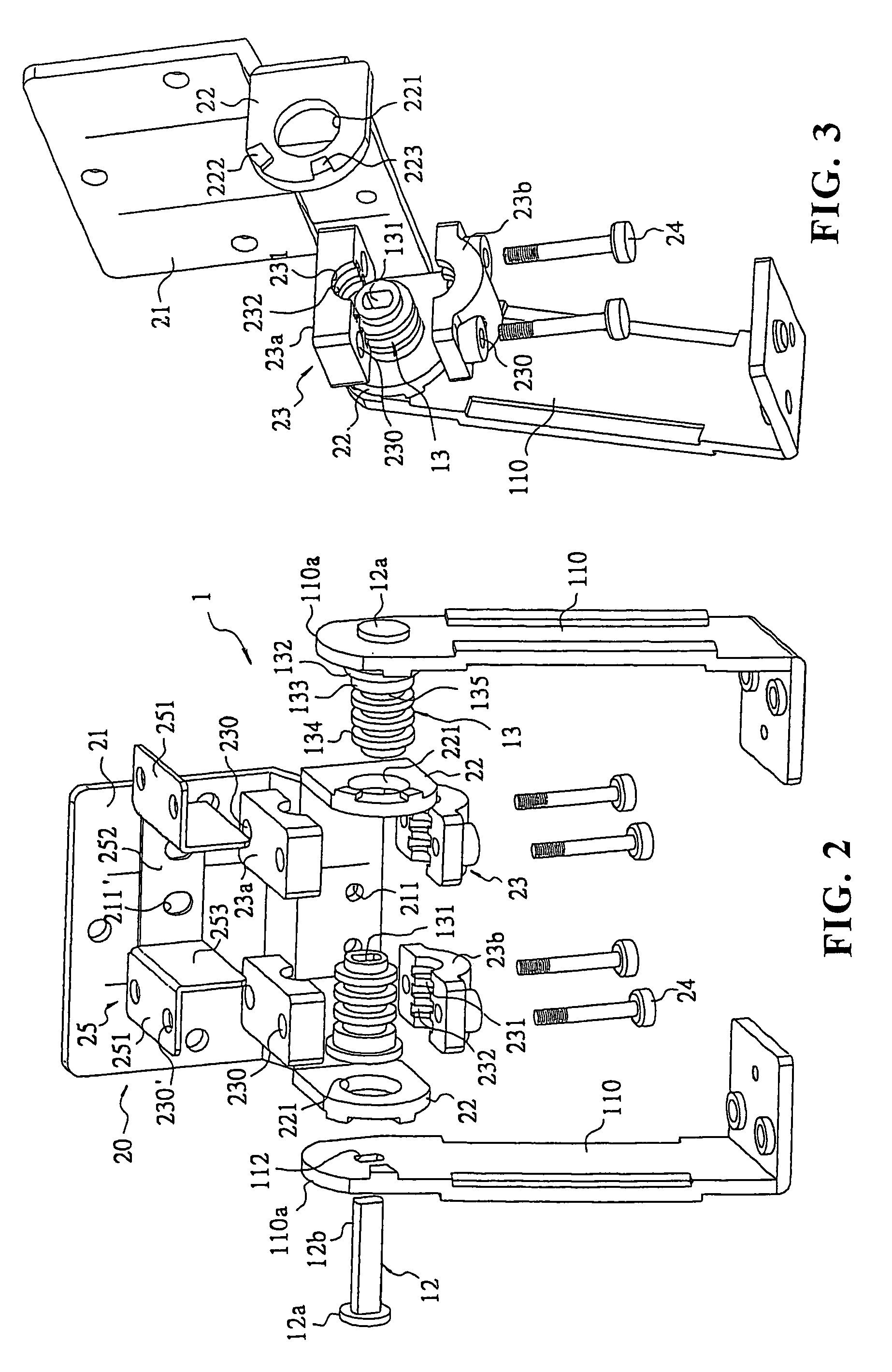
[0026]With reference to FIGS. 2, 3 and 4, a hinge device (1) for a flat panel display according to the present invention is intended to be connected between a flat panel display and a base of the display monitor, such as a liquid crystal display monitor (LCD monitor), a liquid crystal display television (LCD TV), whereby the display panel is able to be adjusted and retained at any desired angles.

[0027]The hinge device (1) comprises a fixed unit (10) and a pivotal unit (20), wherein the fixed unit (10) includes a base (11) and a pair of supports (110), a pair of metal spindles (12), a pair of bushings (13), and the pivotal unit (20) includes a mounting part (21) integrated with...


PUM


Abstract

A hinge device for a flat panel display which is able to be adjusted and retained at any desired angle, comprises a fixed unit and a pivotal unit, wherein the fixed unit has a base, a pair of supports, a pair spindles and a pair of bushings mounted around the spindle, the pivotal unit includes a mounting part integrated with two pivotal bearing parts, two pair of bearing blocks respectively mounted around the bushings and a connecting member, a plurality of annular grooves being defined around an aperture defined in a center of the bearing blocks corresponding to the plurality of the annular ribs formed around the external surface of the bushing, thereby the pivotal unit is able to be retained at any desired angle by the friction between the contacting surfaces of the bearing blocks and the bushing.

Description

BACKGROUND OF THE INVENTION[0001]1. Field of the Invention[0002]The present invention relates to a hinge device for-a flat panel display, and more particularly to a novel hinge device, which enables the display panel to be adjusted and retained at any desired angle.[0003]2. Description of Related Art[0004]As known in the art, common flat panel displays such as liquid crystal display (LCD), and thin-film transistor (TFT) liquid crystal display etc. are widely used incorporating with PC personal computers or NB notebook computers or the likes due to its lightweight and small thickness and small size properties. A known hinge device used between a display panel and a pedestal base generally comprises a spindle extending through connecting parts respectively provided at pivotal ends of the display panel and the base, and disc washers and screw nuts mounted around the spindle, whereby a friction is produced while the display panel pivots with respect to the base. Alternatively, the displ...

Claims


Application Information

Patent Timeline
Patent Type & Authority Patents(United States)
IPC IPC(8): E05C17/64
CPCG06F1/1681G06F1/1616E05D11/082E05Y2900/606Y10T16/54038Y10T16/54034E05Y2999/00
Inventor LIN, KUAN LI
Owner JIIN MING IND
Learn More