Battery power supply device

Inactive Publication Date: 2006-09-26
PANASONIC CORP +1
View PDF11 Cites 27 Cited by
  • Summary
  • Abstract
  • Description
  • Claims
  • Application Information

AI Technical Summary

Benefits of technology

[0021]In the above-described battery power supply device according to the present invention, the space in the case can be fully used as an exhaust path and the electronic element provided in the space of the case can be prevented from being deteriorated, etc., by dew condensation.
[0023]Thus, the invention described herein makes possible the advantages of providing: (1) a battery power supply device which can efficiently and uniformly cool battery modules by improving the cooling ability which prevents nonuniform cooling of the battery modules; (2) a battery power supply device which can prevent electronic elements in a battery pack from being deteriorated by dew condensation.

Problems solved by technology

As a result, flow velocity distribution of the air is not uniform in the holder 4, thereby causing the flow rate of the air to be nonuniform.
Further, layouts of the inlet and outlet ducts 6 and 7 are designed such that considerable pressure loss of the air is caused, and therefore the battery modules 3 in the holder 4 are not efficiently and uniformly cooled.
As a result, the battery modules 3 in the holder 4 are not efficiently cooled.
When dew is formed through condensation due to temperature fluctuations and the presence of moisture in the case 1, these electronic elements can be easily rusted, short-circuited or deteriorated.
Any of these problems causes reduction in the performance of the conventional battery pack 2.

Method used


Image

  • Battery power supply device
  • Battery power supply device
  • Battery power supply device

Examples


Embodiment Construction

[0028]Hereinafter, examples of the present invention are described with reference to the drawings.

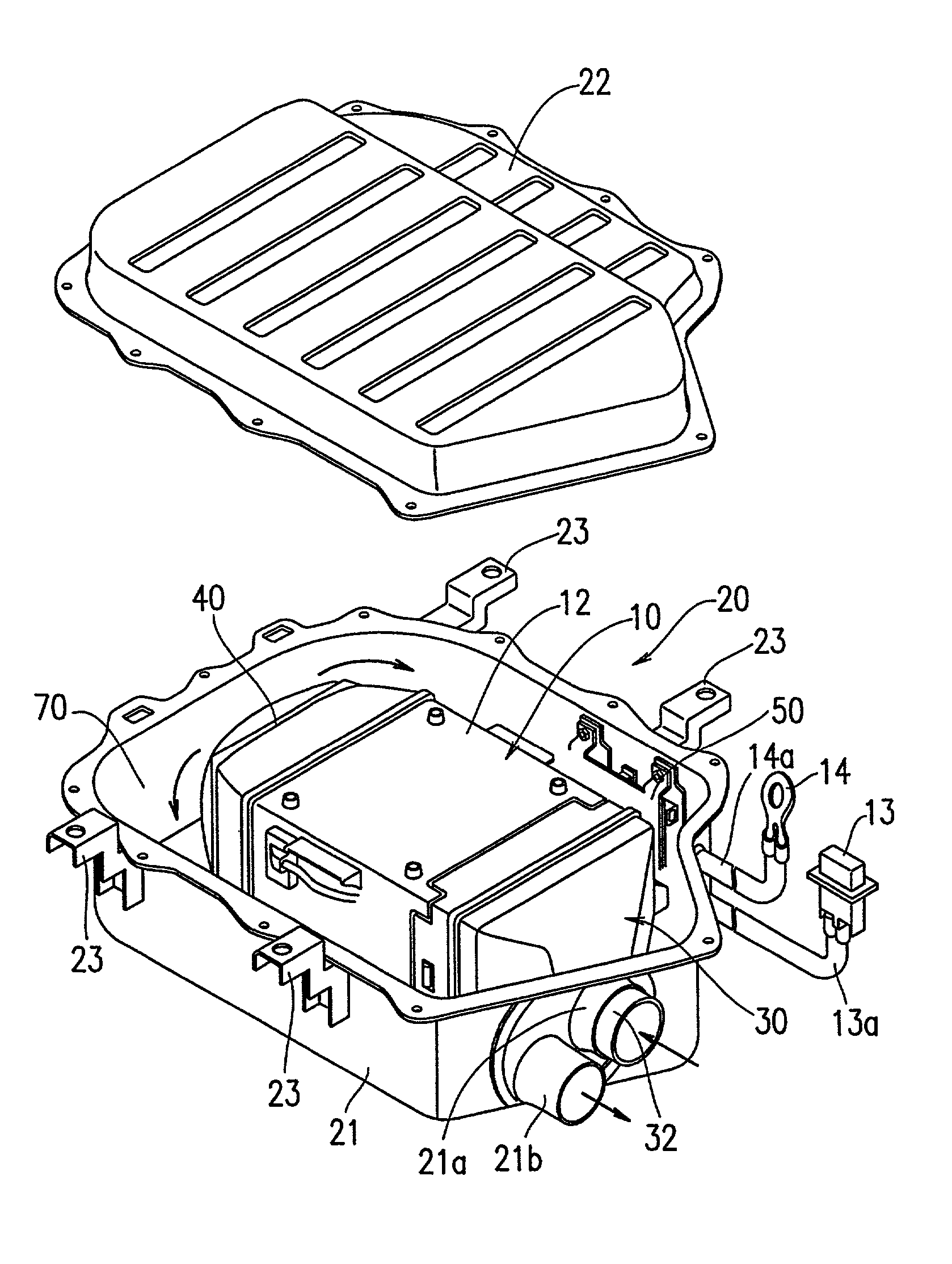
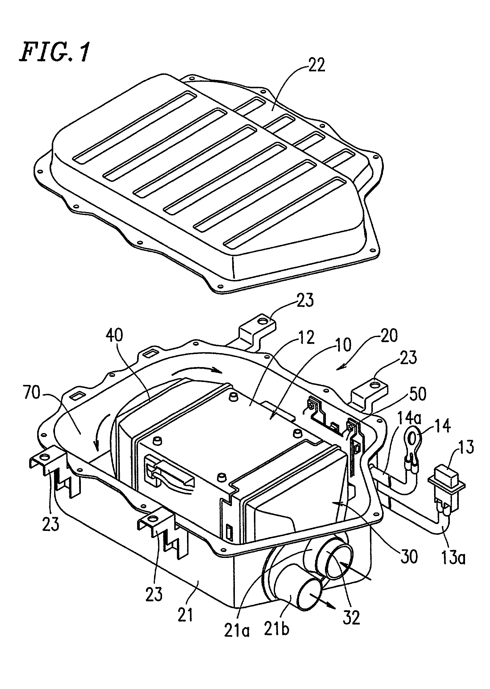
[0029]FIG. 1 is an exploded perspective view showing an example of a battery power supply device according to the present invention. This exemplary battery power supply device according to the present invention is mounted on, for example, a HEV and includes: a battery pack 10 as a high voltage power source; a case 20 for housing the battery pack 10; a duct 30 provided at an inlet side of the battery pack 10 (hereinafter referred to as the “inlet duct 30”); a hood 40 provided at an outlet side of the battery pack 10 (hereinafter referred to as the “outlet hood 40” or “cooling means 40”); and an electronic element 50 for a battery pack which is housed in the case 20 together with the battery pack 10.

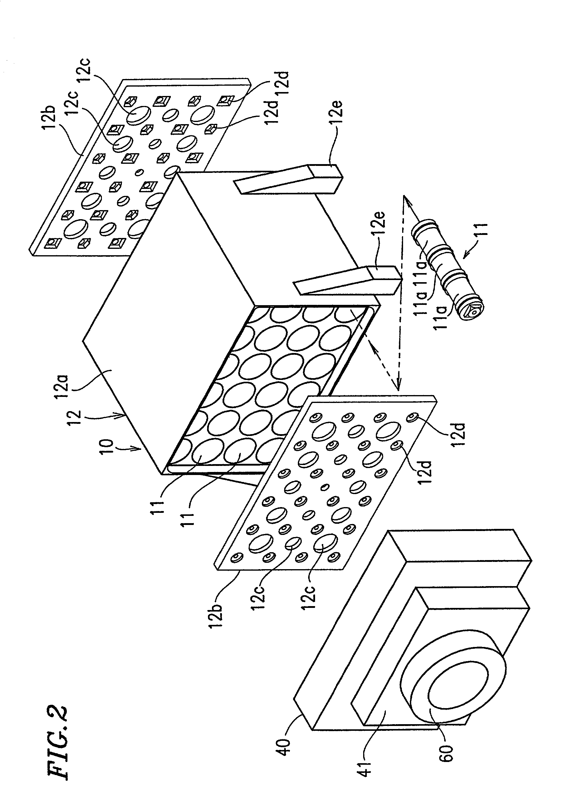
[0030]FIG. 2 is a perspective view of the battery pack 10 and elements provided in the vicinity of the battery pack 10, as viewed from the outlet side of the battery power supply device. As sh...


PUM


Abstract

A battery power supply device of the present invention includes a battery pack in which a plurality of battery modules each includes a plurality of cells which are serially connected together both electrically and mechanically, the plurality of battery modules housed in a holder, and the battery power supply device is structured so that a cooling medium flows around each cell and / or each battery module; the battery back is provided with a plurality of vent holes having different aperture areas which are distributed over at least one of inlet and outlet sides of the battery pack such that a cooling medium having a substantially uniform flow rate flows around each cell and / or each battery module.

Description

BACKGROUND OF THE INVENTION[0001]1. Field of the Invention[0002]The present invention relates to a battery power supply device preferably used for an electric vehicle, such as a HEV (Hybrid Electric Vehicle), PEV (Pure Electric Vehicle) or FCEV (Fuel Cell Electric Vehicle), which uses an electric motor as at least a part of a power source.[0003]2. Description of the Related Art[0004]The electric vehicle, such as a HEV, PEV or FCEV, includes a high voltage battery power supply device for driving an electric motor of the electric vehicle. FIG. 3 illustrates a schematic structure of a conventional battery power supply device.[0005]The conventional battery power supply device shown in FIG. 3 includes a battery pack 2 housed in a case 1. The battery pack 2 includes a plurality of battery modules 3 each provided in the form of a rod and a holder 4 in which the plurality of battery modules 3 are three-dimensionally disposed so as to be parallel to one another. Each battery module 3 include...

Claims


Application Information

Patent Timeline
IPC IPC(8): H01M2/10H01M2/12H01M10/60H01M10/613H01M10/617H01M10/625H01M10/652H01M10/6556H01M10/6563H01M50/213H01M50/50
CPCH01M2/1077H01M10/5004H01M10/5073H01M10/503H01M10/5038H01M10/5067H01M10/5016H01M2/12H01M2/20H01M10/5071H01M10/625H01M10/6563H01M10/652H01M10/643H01M10/6565H01M10/6566H01M10/613Y02E60/10H01M50/30H01M50/50H01M50/213
Inventor KIMOTO, SHINYAKOBAYASHI, TAKAKIWATANABE, KO
Owner PANASONIC CORP
Why Eureka
Try Eureka